Casing pipeline structure

A casing and pipeline technology, which is applied in the field of casing pipeline structure, can solve the problems of bleeding without any countermeasures and the decline of concrete structure strength, and achieve the effects of simplification, strength maintenance and corrosion inhibition

Inactive Publication Date: 2016-08-24
TOTAKU IND INC
View PDF6 Cites 0 Cited by
  • Summary
  • Abstract
  • Description
  • Claims
  • Application Information

AI Technical Summary

Problems solved by technology

That is, the PC steel is corroded by the direct contact of the bleeding water remaining in the pipeline with the PC steel material, or the condensation generated in the gap part after the bleeding water evaporates, and the strength of the concrete structure is reduced. Happening
However, the current situation is that no countermeasures have been taken against the bleeding that occurs in the pipeline when the cement slurry hardens.

Method used


Image

  • Casing pipeline structure
  • Casing pipeline structure
  • Casing pipeline structure

Examples


Embodiment Construction

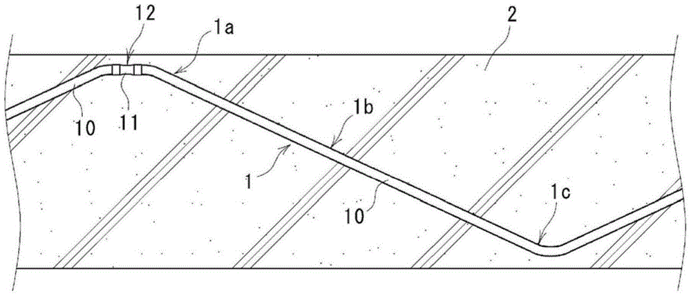
[0056] Embodiments of this invention will be described in detail below with reference to the drawings. The casing pipe structure according to one embodiment of the present invention is suitable for construction of prestressed concrete structures such as PC girder bridges produced by post-tensioning methods.

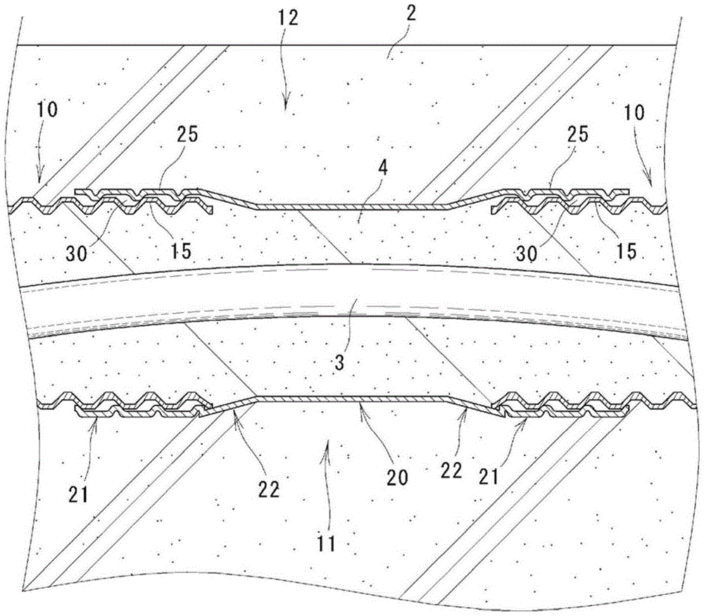
[0057] Such as figure 1 as well as figure 2 As shown, the casing pipeline 1 is buried in the concrete structure 2, and the PC steel material 3 for introducing prestress to the concrete structure 2 is inserted through the casing pipeline 1, and the casing pipeline 1 The inside is filled with cement slurry4. In addition, as the cement slurry 4, general cement slurry composed of a mixture of Portland cement, water, admixture, and the like is used.

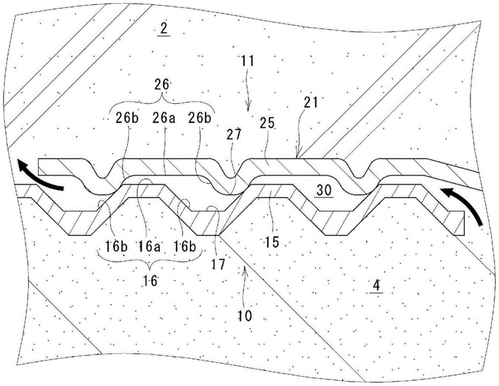
[0058] The bushing pipeline 1 is buried in the concrete structure 2 in a meandering state in the up-down direction, and a connecting portion 12 is provided near the top 1 a of the casing pipeline 1 . The connection between t...


PUM


Abstract

The purpose of the present invention is, in a sheath conduit in which a PC steel member is inserted and that is filled with grout, to prevent corrosion of the PC steel member caused by bleed water by isolating the bleed water, which is produced inside the conduit when the grout cures, or allowing the same to escape. This sheath conduit (1) comprises connection sites (12) where ends of sheaths (10) are coupled and fixed via a joint member (11). In the connection site (12), a connecting tube (21) of the joint member (11) is fit around and fixed to the end of the sheath (10) by screwing together a ridge (15) of the sheath (10) and a projection (25) of the joint member (11) while the outer peripheral face (16) of the ridge (15) and the inner circumferential face (26) of the projection (25) are in partial contact with each other, and a water discharge channel (30) for guiding bleed water, which is produced inside the conduit when grout (4) cures, to the exterior of the conduit is formed between the end of the sheaths (10) and the connecting tubes (21) of the joint members (11).

Description

technical field [0001] The invention relates to a casing pipeline structure. The casing pipeline is buried in a concrete structure such as a PC girder bridge, and PC steel materials for introducing prestress into the concrete structure are inserted through the casing pipeline. , and the inside of the casing pipeline is filled with cement slurry. Background technique [0002] Generally, in the case of building a prestressed concrete structure such as a PC girder bridge manufactured by the post-tensioning method, the casing pipe is buried in the concrete structure, and the PC steel inserted in the pipe is tensioned. , so that the compressive force (prestress) as its reaction force is introduced into the concrete structure. Then, cement slurry, which is a mixture of Portland cement, water, admixture, etc., is filled into the pipeline through which the PC steel material is inserted, and hardened to protect the PC steel material from corrosion. [0003] When filling the grout, ...

Claims


Application Information

Patent Timeline
Patent Type & Authority Patents(China)
IPC IPC(8): E04C5/10E01D1/00
CPCE04C5/10
Inventor 菊森康博那波恒博
Owner TOTAKU IND INC
Why Eureka
Try Eureka