Floor structure of vehicle body center section

a technology of floor structure and vehicle body, which is applied in the direction of movable seats, roofs, dismountable/non-movable seats, etc., can solve the problems of insufficient rigidity of the front side portion of the rear floor panel, and achieve the effect of enhancing the rigidity of the mounting portion of the rear seat leg, efficiently absorbing and diffusing, and smoothly transmitting the momen

Active Publication Date: 2015-04-14
SUZUKI MOTOR CORP
View PDF23 Cites 0 Cited by
  • Summary
  • Abstract
  • Description
  • Claims
  • Application Information

AI Technical Summary

Benefits of technology

[0006]The present invention has been made in the light of the circumstances as above, and an object of the present invention is to provide a floor structure of a vehicle body center section that can efficiently absorb and diffuse a load when the load exerted on the upper portion of the rear seat becomes a moment and is transmitted to a mounting portion of a rear seat leg by enhancing rigidity of the mounting portion of the rear seat leg, and is capable of suppressing a local deformation of the rear floor panel that is located at the mounting portion of the rear seat leg and rotation of the mounting portion of the rear seat leg to the vehicle front side, and reducing a moving amount of the rear seat to the vehicle front side.

Problems solved by technology

However, in the conventional floor structure of the vehicle body center section described above, the rear floor panel is of an open section structure, and the rigidity of the front side portion of the rear floor panel is insufficient.
Therefore, when the rear seat is displaced toward the vehicle front side by an impact load from the vehicle front side, the load that is exerted on the upper portion of the rear seat becomes a moment, the rear floor panel located at the mounting portion of the rear seat leg is locally deformed, the mounting portion of the rear seat leg rotates toward the vehicle front side and cannot support the rear seat, and thus the rear seat is likely to move to the vehicle front side to a large extent.

Method used


Image

  • Floor structure of vehicle body center section
  • Floor structure of vehicle body center section
  • Floor structure of vehicle body center section

Examples


Embodiment Construction

[0022]Hereinafter, the present invention will be described in detail based on an illustrated embodiment.

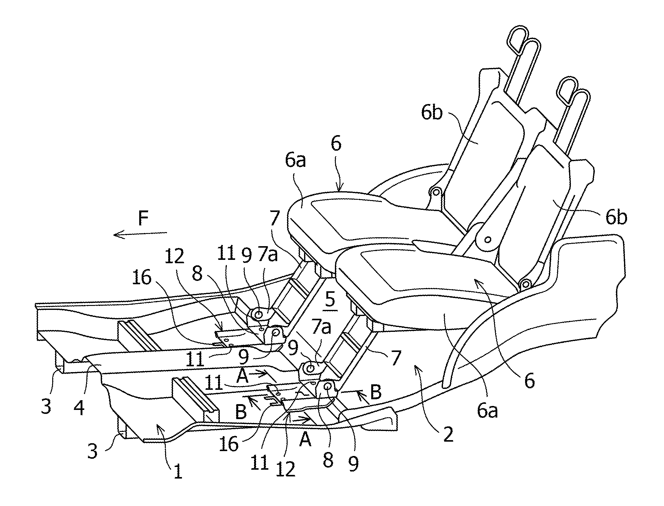
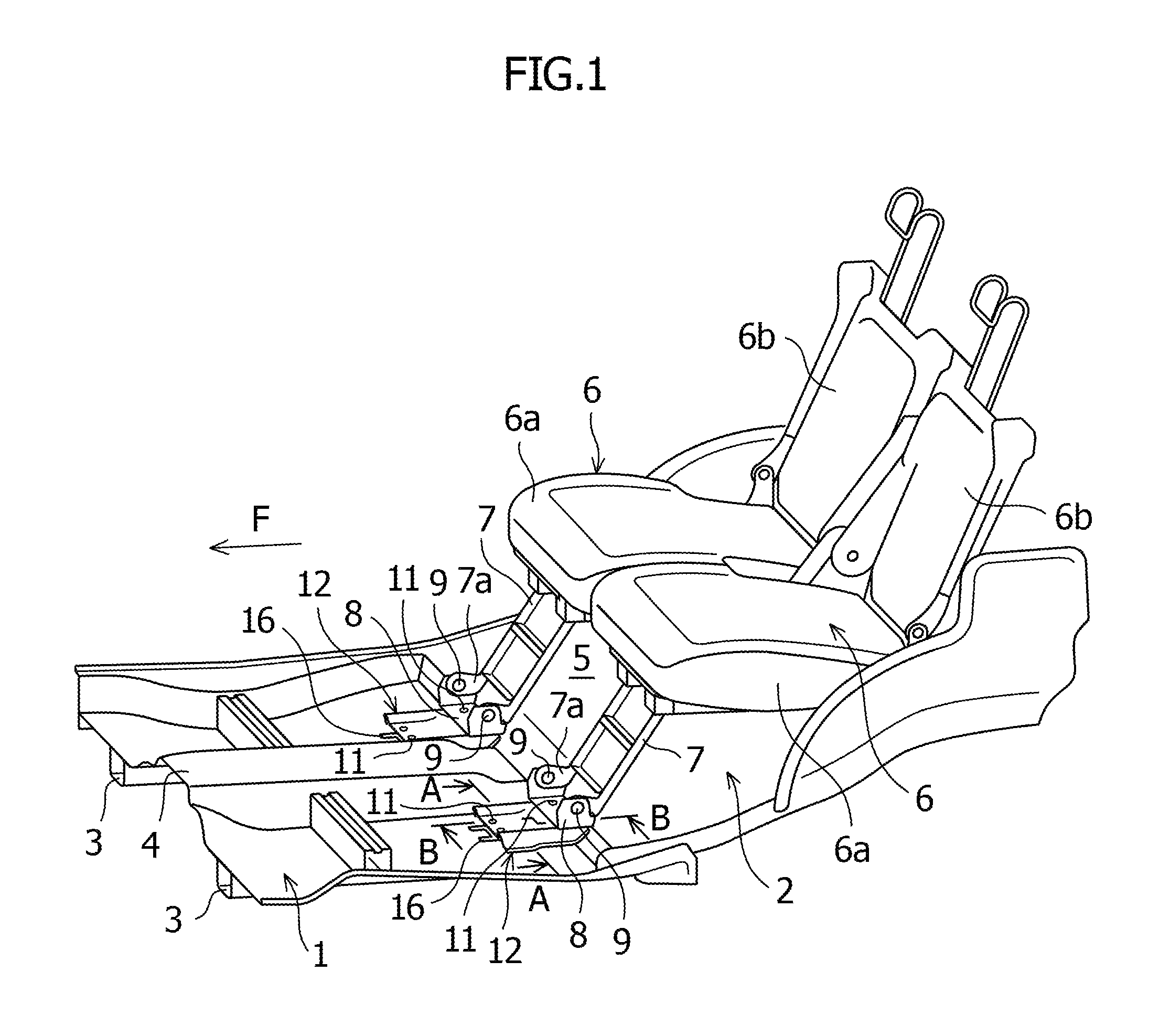
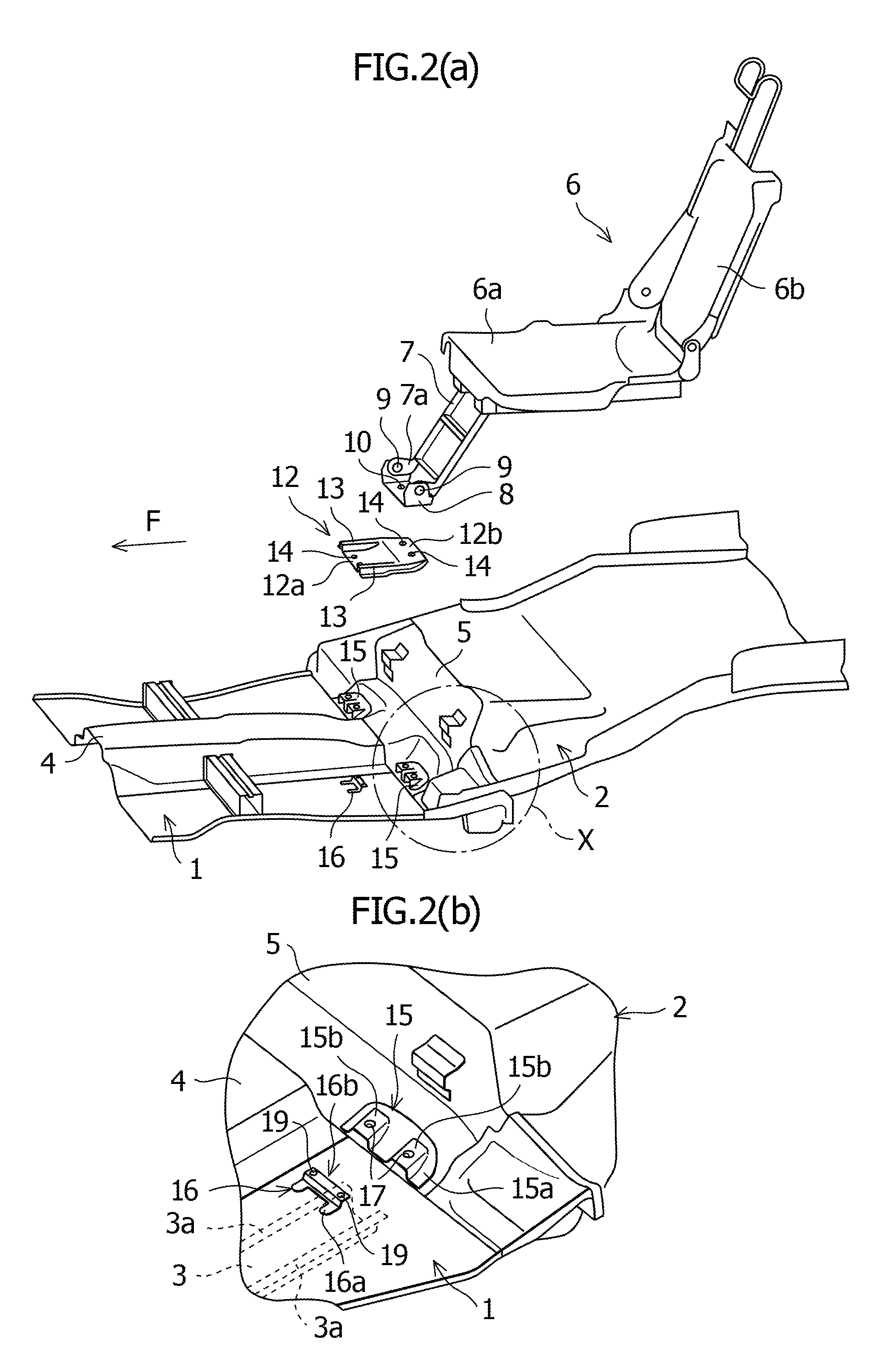
[0023]FIG. 1 to FIG. 4 show a floor structure of a vehicle body center section according to the embodiment of the present invention.

[0024]The floor structure of a vehicle body center section of a vehicle according to the embodiment of the present invention includes a main floor panel 1 and a rear floor panel 2 that are provided in a vehicle longitudinal direction, a rear portion of the main floor panel 1 and a front portion of the rear floor panel 2 are joined to each other in a state in which the rear portion and the front portion are overlaid on each other, as shown in FIG. 1 to FIG. 4. At lower portions at both left and right sides in a vehicle width direction of the main floor panel 1, floor side members 3 that are rigid members extending in the vehicle longitudinal direction are respectively provided. These floor side members 3 are formed to be hat-shaped in section, and are ...


PUM


Abstract

In a floor structure of a vehicle body center section, a floor side member is provided at lower portions of a main floor panel, a vertical wall is formed at a front side of a rear floor panel, a rear seat is installed on the rear floor panel, a rear seat leg extends downward along the vertical wall, a lower end portion of the rear seat leg is mounted to a portion of the rear floor panel, a rear seat leg reinforcement member that extends in a vehicle longitudinal direction is disposed on each of upper portions at both left and right sides of the floor panels, a rear end portion of the reinforcement member is connected to the lower end portion of the rear seat leg, and a front end portion of the reinforcement member is connected to the main floor panel and the floor side member.

Description

CROSS-REFERENCE TO RELATED APPLICATIONS[0001]The present application claims priority from JP 2012-128971 filed in the Japanese Patent Office on Jun. 6, 2012, the disclosure of which is hereby incorporated herein by reference.BACKGROUND OF THE INVENTION[0002]The present invention relates to a floor structure of a vehicle body center section to which a rear seat is mounted.[0003]Conventionally, a floor structure of a vehicle body center section in a vehicle such as an automobile includes a main floor panel and a rear floor panel that are provided along a vehicle longitudinal direction, and a front portion of the rear floor panel is joined to a rear portion of the main floor panel. At a front side of the rear floor panel, a vertical wall that extends upward is formed, and on an upper portion of the rear floor panel located at a rear side of the vertical wall, a rear seat is installed. Furthermore, a fuel tank is disposed in a lower side of the rear floor panel that is located at the re...

Claims


Application Information

Patent Timeline
Patent Type & Authority Patents(United States)
IPC IPC(8): B62D25/20B60N2/30B60N2/90
CPCB62D25/20B60N2/305B60N2/3065
Inventor JOJIKI, KENTAROHASHIBA, YUKAWAI, KEISUKE
Owner SUZUKI MOTOR CORP
Why Eureka
Try Eureka