
Acceleration pedal for vehicle

a technology for acceleration pedals and vehicles, applied in the direction of vehicle sub-unit features, mechanical control devices, instruments, etc., can solve the problems of complex structure, increased fatigue of users, and increased complexity of components, so as to reduce fatigue, increase convenience in repair, and high user satisfaction

Active Publication Date: 2021-09-21
HYUNDAI MOTOR CO LTD +1
View PDF14 Cites 0 Cited by
  • Summary
  • Abstract
  • Description
  • Claims
  • Application Information

AI Technical Summary

Benefits of technology

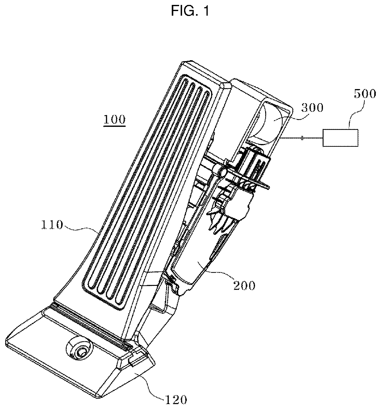
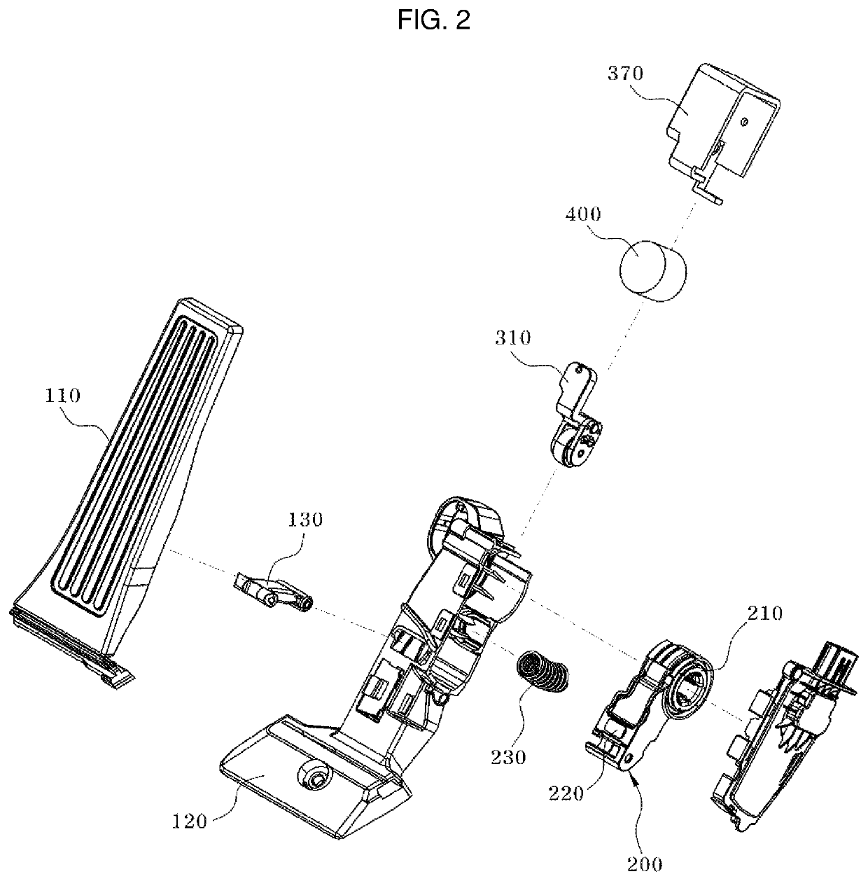
[0014]According to the present disclosure, the following effects may be obtained through the combination and usage relationships between the above-described exemplary embodiment and the configuration to be described below. The present disclosure has effects to provide the accelerator pedal for the vehicle having high user satisfaction by providing effects to apply the foot effort to the pedal part through a simplified structure.
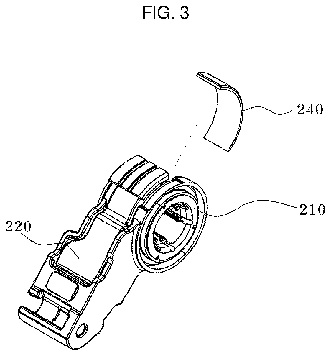
[0015]Further, the present disclosure has effects to provide the accelerator pedal for the vehicle having an increased convenience in repair by facilitating replacement of the friction member positioned on the arm assembly. Further, the present disclosure provides effects to reduce the user's fatigue even in a long-term driving.

Problems solved by technology

The mechanical accelerator pedal causes an operational problem due to a surrounding environment, temperature change, cable deterioration, and so on.
Further, to reduce the driver's fatigue due to the operation of the electronic accelerator pedal, hysteresis is required to be created.
As a foot effort creation technology applied to the electronic accelerator pedal in the related art, systems for providing a foot effort using a rotary motor and a plurality of gears have been developed, but they have complex structures and require an increased number of components.

Method used


Image

  • Acceleration pedal for vehicle
  • Acceleration pedal for vehicle
  • Acceleration pedal for vehicle

Examples


Embodiment Construction

[0025]It is understood that the term “vehicle” or “vehicular” or other similar term as used herein is inclusive of motor vehicles in general such as passenger automobiles including sports utility vehicles (SUV), buses, trucks, various commercial vehicles, watercraft including a variety of boats and ships, aircraft, and the like, and includes hybrid vehicles, electric vehicles, plug-in hybrid electric vehicles, hydrogen-powered vehicles and other alternative fuel vehicles (e.g. fuels derived from resources other than petroleum). As referred to herein, a hybrid vehicle is a vehicle that has two or more sources of power, for example both gasoline-powered and electric-powered vehicles.

[0026]The terminology used herein is for the purpose of describing particular embodiments only and is not intended to be limiting of the disclosure. As used herein, the singular forms “a”, “an” and “the” are intended to include the plural forms as well, unless the context clearly indicates otherwise. It wi...


PUM


Abstract

An accelerator pedal for a vehicle is provided, which includes a member that is fixed to a bottom of the vehicle, a pedal part that is pivotally fastened to an upper surface of the member, and an arm assembly that is positioned on the member and configured to be rotated based on an input onto the pedal part. A spring is configured to come in contact with the arm assembly and a wheel assembly is disposed adjacent to a first end of the arm assembly to provide a foot effort to the arm assembly. A controller is configured to apply the foot effort to the arm assembly in a state where the wheel assembly is configured to selectively come in contact with the first end of the arm assembly.

Description

CROSS-REFERENCE TO RELATED APPLICATION[0001]This application claims under 35 U.S.C. § 119(a) the benefit of priority to Korean Patent Application No. 10-2019-0165178 filed on Dec. 12, 2019, the entire contents of which are incorporated herein by reference.BACKGROUND(a) Technical Field[0002]The present disclosure relates to an acceleration pedal for a vehicle, and more particularly, to an accelerator pedal for a vehicle having a foot effort generation structure that corresponds to an input onto a pedal part.(b) Background Art[0003]An accelerator pedal enables a user to accelerate the rotation of an engine. The user engages the accelerator pedal by exerting force onto the pedal to increases the rotating speed of the engine, and disengages the accelerator pedal to decrease the rotating speed of the engine. The accelerator pedal is connected to a throttle valve through a wire and a linkage. When the user engages the accelerator pedal, the throttle valve is opened to suction air into a c...

Claims


Application Information

Patent Timeline
Patent Type & Authority Patents(United States)
IPC IPC(8): G05G1/30B60K26/02B60K26/04G05G1/44G05G5/05B60T7/06B60T7/04
CPCB60K26/021B60K2026/023B60Y2410/132B60K26/02G05G1/30
Inventor KIM, YEONG JIKPARK, JOON YOUNG
Owner HYUNDAI MOTOR CO LTD
Learn More