Control device, robot and control method

a control device and robot technology, applied in the direction of electric programme control, program control, instruments, etc., can solve the problems of damage or breaking of the screw hole, and the inspection cannot be performed, so as to achieve the alignment easily and accurately, and easily and accurately insert the screw gauge into the screw hol

Active Publication Date: 2021-09-21
SEIKO EPSON CORP
View PDF14 Cites 0 Cited by
  • Summary
  • Abstract
  • Description
  • Claims
  • Application Information

AI Technical Summary

Benefits of technology

[0009]According to such a control device according to the aspect of the invention, it is possible to easily and accurately achieve the alignment between the screw gauge and the screw hole, and thus, it is possible to easily and accurately insert the screw gauge into the screw hole.
[0032]According to such a control method according to the aspect of the invention, it is possible to easily and accurately achieve the alignment between the screw gauge and the screw hole, and thus, it is possible to easily and accurately insert the screw gauge into the screw hole.

Problems solved by technology

However, in the thread inspection device described in Document 1, there exist the following problems.
Firstly, if the positions of the limit gauge for screw thread and the screw hole do not completely coincide with each other, the limit gauge for screw thread cannot be inserted into the screw hole, and thus, the inspection cannot be performed.
Further, in the case in which there is eccentricity in the limit gauge for screw thread or the thread inspection device, there is a possibility of damaging or breaking the screw hole with the limit gauge for screw thread when screwing the limit gauge for screw thread in the screw hole.

Method used


Image

  • Control device, robot and control method
  • Control device, robot and control method
  • Control device, robot and control method

Examples


first embodiment

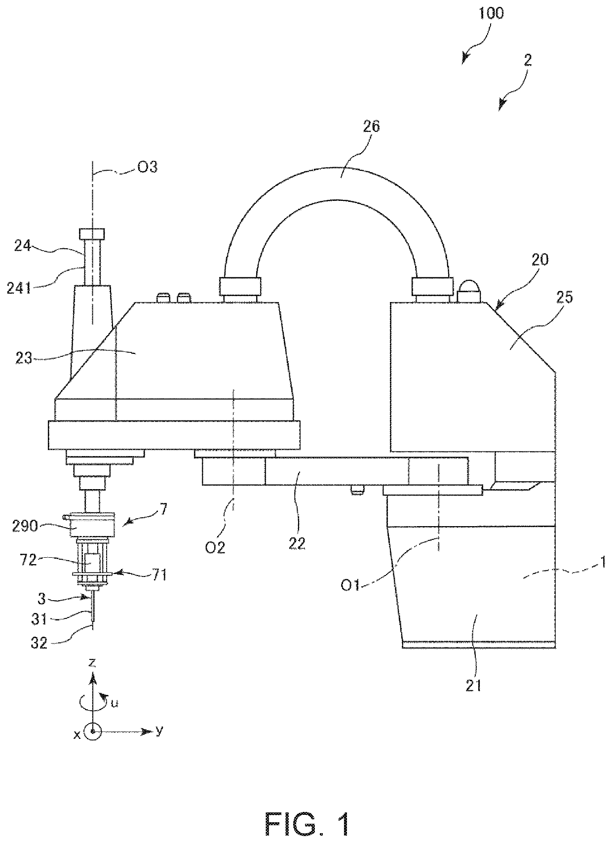
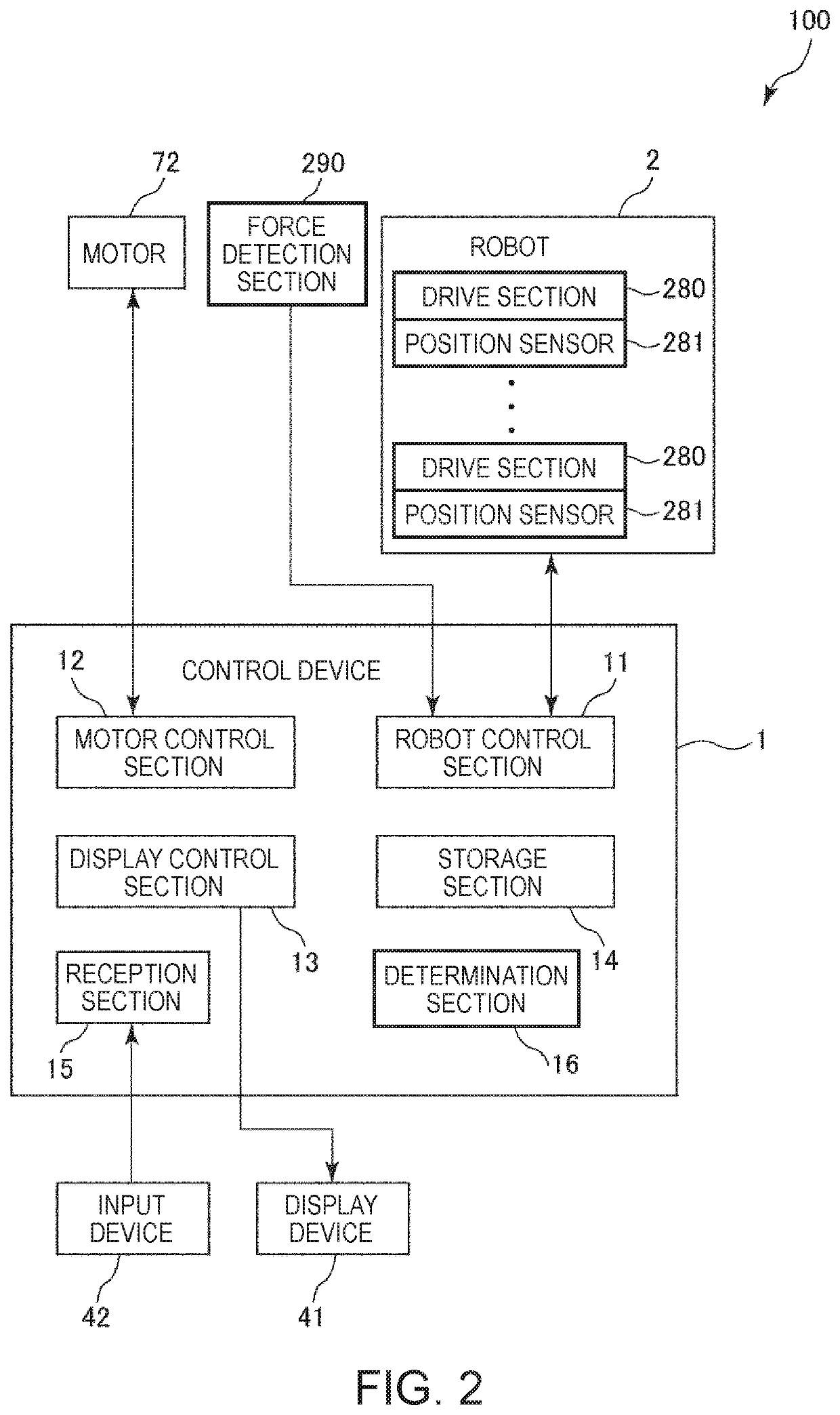
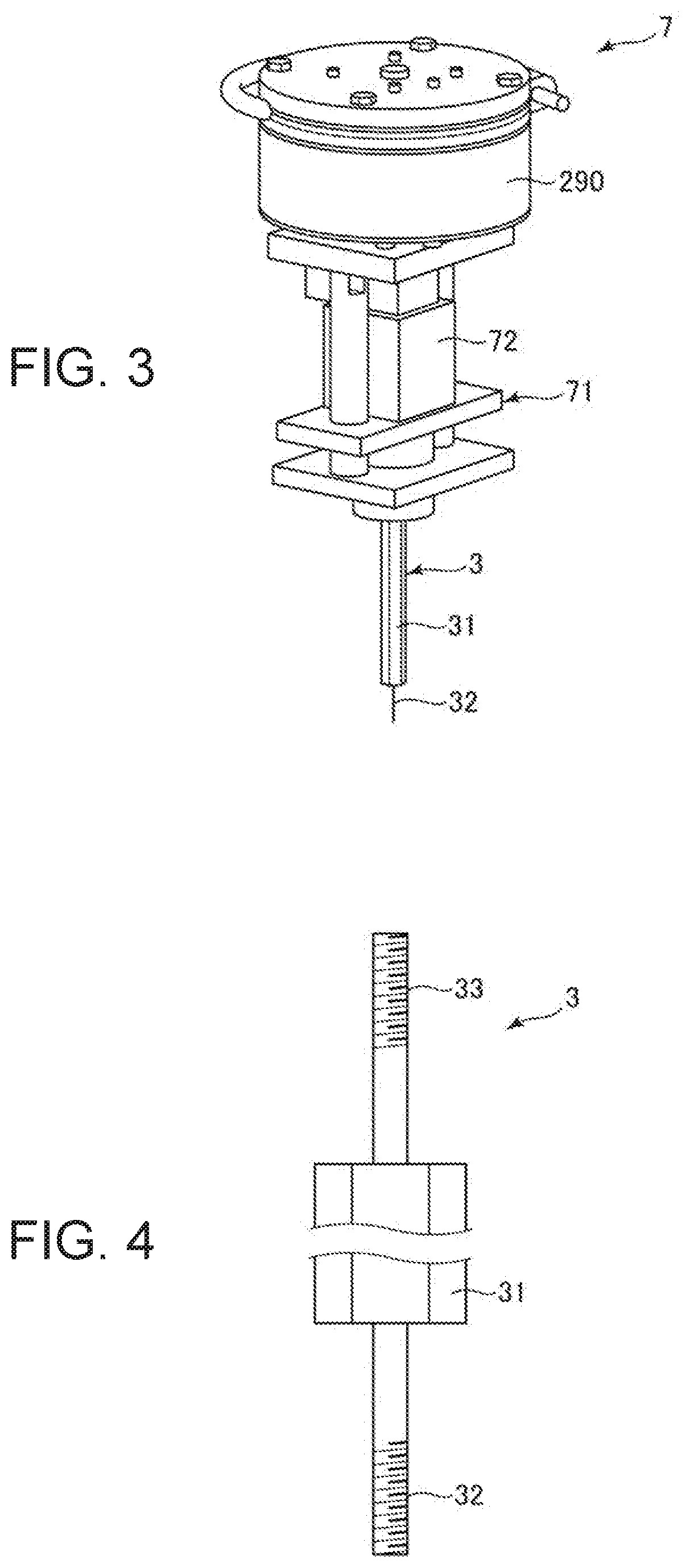
[0055]FIG. 1 is a side view showing a robot according to a first embodiment of the invention, and a robotic system equipped with the robot according to the first embodiment. FIG. 2 is a block diagram of the robotic system shown in FIG. 1. FIG. 3 is a perspective view of an end effector of the robotic system shown in FIG. 1. FIG. 4 is a side view of a limit gauge for screw thread of the end effector of the robotic system shown in FIG. 1. FIG. 5 and FIG. 6 are each a flowchart showing a control operation in an inspection of the screw hole of the control device of the robotic system shown in FIG. 1. FIG. 7 through FIG. 10 are each a diagram for explaining the inspection of the screw hole performed by the robotic system shown in FIG. 1. FIG. 11 is a graph showing force in a z-axis direction detected by a force detection section in the inspection of the screw hole performed by the robotic system shown in FIG. 1. FIG. 12 is a diagram showing a window displayed on a display device of the r...

second embodiment

[0166]FIG. 13 is a side view showing a robot according to a second embodiment of the invention, and a robotic system equipped with the robot according to the second embodiment.

[0167]FIG. 14 and FIG. 15 are each a flowchart showing a control operation in an inspection of the control device of the robotic system shown in FIG. 13.

[0168]The second embodiment will hereinafter be described focusing mainly on the differences from the embodiment described above, and the description of substantially the same matters will be omitted.

[0169]As shown in FIG. 13, in the second embodiment, an end effector 7A is detachably connected to the tip part of the shaft 241.

[0170]The end effector 7A has the force detection section 290, an attachment part 73 attached to the force detection section 290, and the limit gauge for screw thread 3 detachably attached to the attachment part 73. In other words, the end effector 7A does not have a motor. In the end effector 7A, the force detection section 290 is detac...

third embodiment

[0204]FIG. 16 is a diagram for explaining the inspection of the screw hole in a third embodiment of the invention.

[0205]FIG. 17 and FIG. 18 are each a flowchart showing a control operation of a control device in an inspection of the screw hole in the third embodiment.

[0206]The third embodiment will hereinafter be described focusing mainly on the differences from the embodiments described above, and the description of substantially the same matters will be omitted.

[0207]As shown in FIG. 16, in the third embodiment, the screw hole 83 (the internal thread) as the inspection object is a screw hole (a through hole) provided to the work 81 and penetrating the work 81. The inspection of the penetrating screw hole 83 is different in the method (how to make the decision to pass or fail) of the inspection of the GO aspect from the inspection of the bottomed screw hole 82 described above.

[0208]Then, the operation (a control operation of the control device 1) of the robotic system 100 in the in...


PUM


Abstract

A control device adapted to control a robot including a robot arm provided with a force detector includes a processor that is configured to execute computer-executable instructions so as to control the robot, wherein the processor is configured to: operate the robot arm to move a screw gauge which is disposed on a tip side of the force detector of the robot arm, used for an inspection of a screw hole, and provided with an external thread, to make the external thread have contact with the screw hole; then detect force applied to the screw gauge using the force detector to perform force control in a direction perpendicular to a direction of an axis of the screw hole based on detection information of the force detector; and operate the robot arm to move the screw gauge based on the force control.

Description

BACKGROUND1. Technical Field[0001]The present invention relates to a control device, a robot and a control method.2. Related Art[0002]Inspection of a screw hole is performed by a worker manually inserting a limit gauge for screw thread in the screw hole to screw the gauge in the screw hole, but in recent years, the automatization thereof is advancing.[0003]In JP-A-2008-261801 (Document 1), there is disclosed a thread inspection device for inspecting the thread (the screw hole) using the limit gauge for screw thread.[0004]In the thread inspection device described in Document 1, the decision to pass or fail is made by rotating the limit gauge for screw thread with a rotary motor while vertically moving the limit gauge for screw thread with a reciprocation device, then inserting the limit gauge for screw thread into the screw hole to screw the limit gauge for screw thread in the screw hole. Specifically, a load current of the rotary motor is detected, and in the case in which the load ...

Claims


Application Information

Patent Timeline
Patent Type & Authority Patents(United States)
IPC IPC(8): G05B15/00G05B19/00G05B19/401B25J9/16G05B19/18G05B19/402
CPCG05B19/401B25J9/1687G05B19/186G05B19/402B25J9/1633G05B2219/37441G05B2219/37606G05B2219/39332G05B2219/39346G05B2219/39529G05B2219/40032G05B2219/45061G05B2219/45091G05B2219/49196B25J9/1602B25J9/1679B25J11/00B25J15/0019G01B3/48
Inventor UEDA, JUNYASHIMADA, YUJI
Owner SEIKO EPSON CORP
Why Eureka
Try Eureka