
Valve for a container

a container and valve cup technology, applied in the field of valves for containers, can solve the problems of difficult to achieve the rigid and sealing connection between the base of the container and the valve cup, deterioration of the content of the container, and undesirable chemical reactions

Active Publication Date: 2021-09-28
ALTACHEM
View PDF55 Cites 0 Cited by
  • Summary
  • Abstract
  • Description
  • Claims
  • Application Information

AI Technical Summary

Benefits of technology

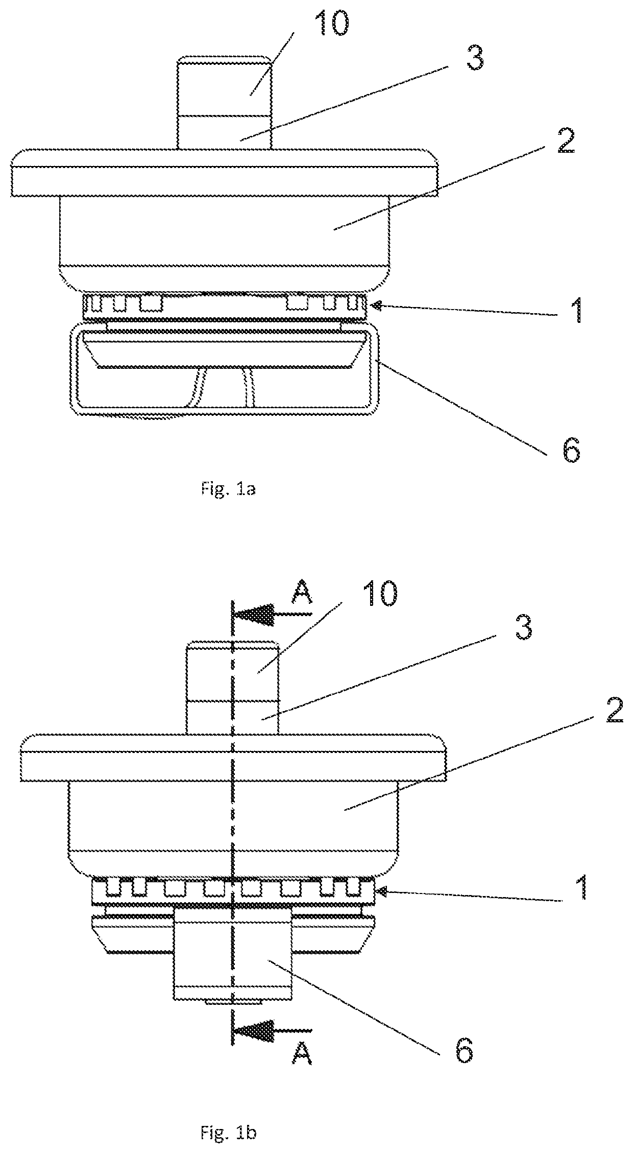
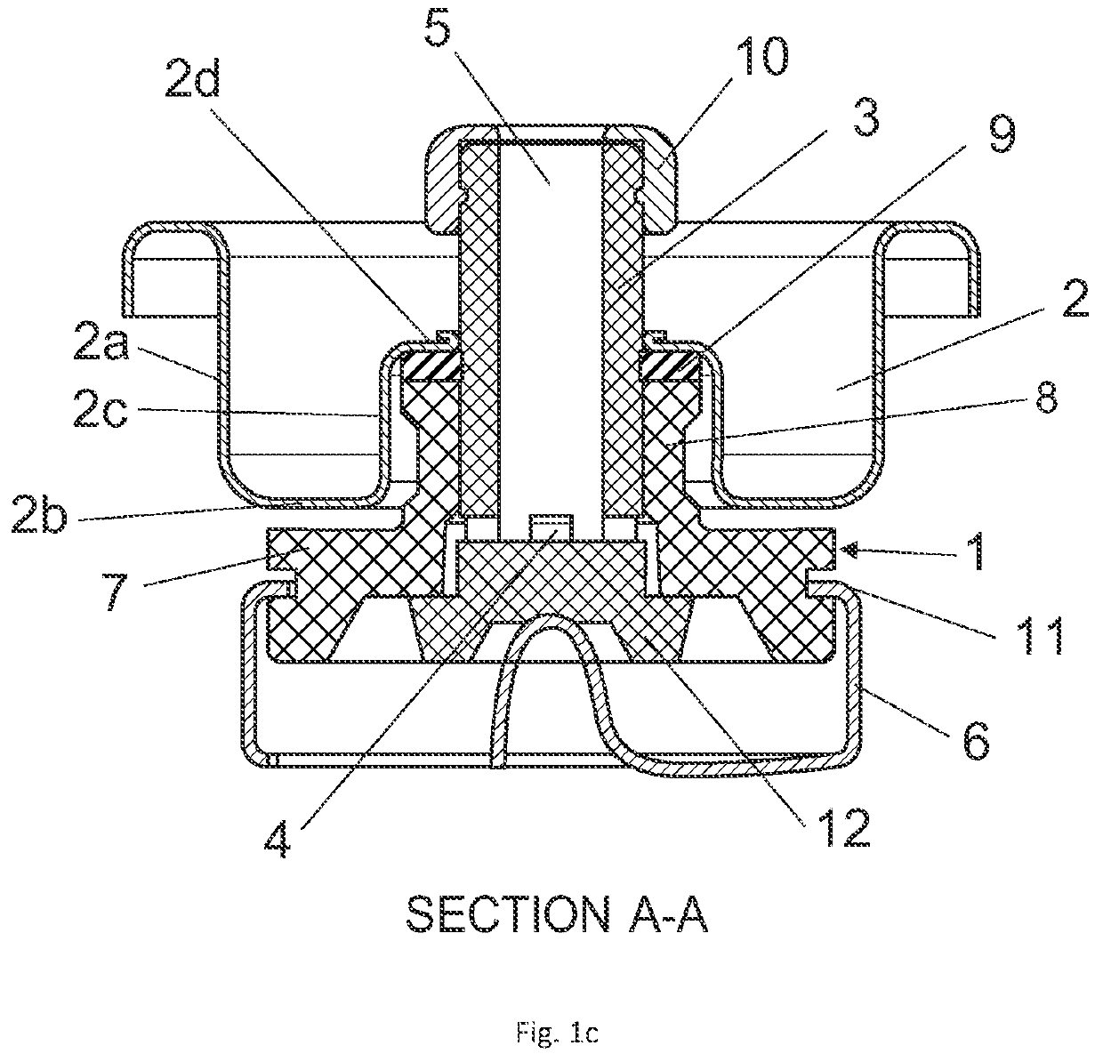
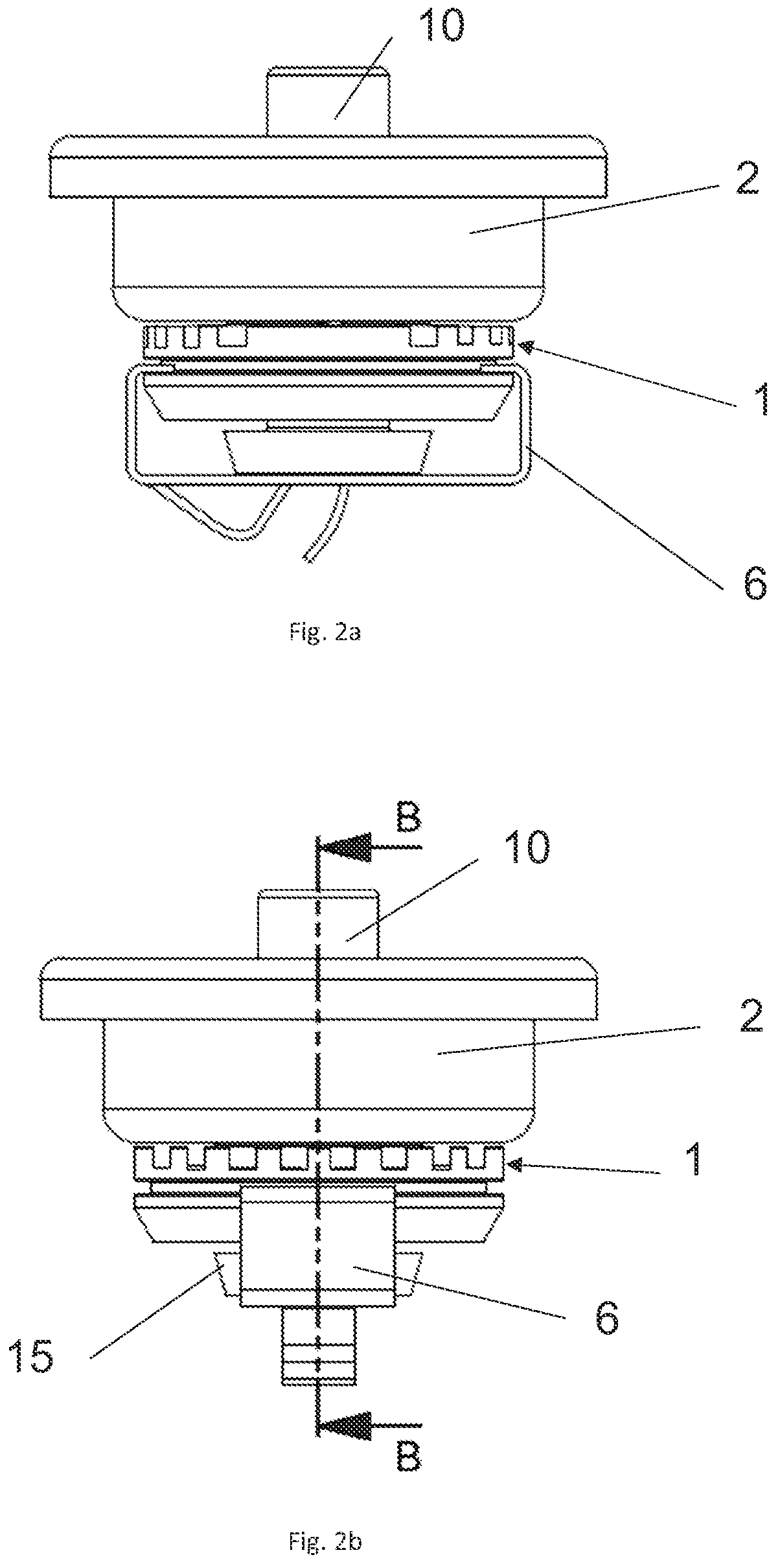
The invention results in a valve with limited creep and minimal permeability, reducing water vapor transfer and sticking to a minimum. The high rigidity of the valve cup is achieved through a circumferential step-like contour. The sealing seals at the same time the valve cup against the housing and the stem against the housing, simplifying the assembly of the valve. The stem is preferably free of split lines in the sealing area. To open the valve, the stem must be pushed downwards with a force higher than the closing force of the spring element, which acts as a limiting spring.

Problems solved by technology

However, the rigid and sealing connection between the base of the housing and the valve cup is difficult to achieve and a second sealing must be provided between the stem and the housing.
It is known in the field of dispenser valves that water vapour entering into the container can deteriorate the content of the container and lead to undesirable chemical reactions thereof.
In the case of polyurethane containers, the polyurethane reacts with the water vapour which leads to the sticking of the dispenser valve.
The stem which is made of hard plastic material (such as high density polyethylene) abutting with its flange against the housing which is also made of hard plastic material results in a lower gas loss than conventional valves using rubber sealing.

Method used


Image

  • Valve for a container
  • Valve for a container
  • Valve for a container

Examples


third embodiment

[0064]In FIGS. 5a / 5b and 6a / 6b, there is also an annular contact between the stem 3 and the housing 1. In this embodiment, the flange 12 of the stem 3 has a conical shape and it abuts in the closed position against a lipseal 14 provided on the housing 1.

[0065]In the embodiments of FIGS. 3a / 3b, 5a / 5b, and 6a / 6b the sealing surface is smaller and consequently the sealing force per surface unit is higher than for the full surface contact between the flange 12 of the stem 3 and the housing 1.

fourth embodiment

[0066]In FIGS. 5a / 5b and 6a / 6b, the top sealing part 10 which is provided around the outlet opening 5 of the stem 3 is implemented in the stem 3 by two-component injection. The soft material of the top sealing part 10 is molded on the harder material of the stem 3.


PUM


Abstract

A valve for a container for dispensing pressurized fluid includes a housing which is mounted on a valve cup, a hollow stem provided in a passage of the housing which stem has at least one lateral inlet opening at its lower end and an outlet opening at its upper end, and a spring. The housing has a circumferential step-like contour with an outer, lower part and a central, upper part. The valve cup follows essentially the step-like contour line of the housing and ends horizontally on the top of the housing close to the stem and a sealing is provided on the upper side of the housing between the housing and the valve cup and which seals at the same time the valve cup against the housing and the stem against the housing.

Description

CROSS REFERENCE TO RELATED APPLICATIONS[0001]This application is the National Stage of PCT / EP2018 / 075519 filed on Sep. 20, 2018, which claims priority under 35 U.S.C. § 119 of Belgium Application No. BE2017 / 5671 filed on Sep. 21, 2017, the disclosure of which is incorporated by reference. The international application under PCT article 21(2) was published in English.BACKGROUND OF THE INVENTION1. Field of the Invention[0002]The invention concerns a valve for a container for dispensing pressurized fluid, said valve comprising a housing which is mounted on a valve cup, a hollow stem provided in a passage of the housing which stem has at least one lateral inlet opening at its lower end and an outlet opening at its upper end, which stem is displaceable between a closed position and an open position and spring means by means of which the stem is pushed in the closed position, wherein the housing has a circumferential step-like contour with an outer, lower part and a central, upper part.2....

Claims


Application Information

Patent Timeline
Patent Type & Authority Patents(United States)
IPC IPC(8): B65D83/48B65D83/38B05B11/00B65D83/20B65D83/30B65D83/32
CPCB65D83/48B65D83/38B05B11/3077B65D83/206B65D83/303B65D83/32B05B11/1077
Inventor POPPE, JEAN-MARIEVANLERBERGHE, NIELS
Owner ALTACHEM
Learn More