MIMO radar sensor for motor vehicles

a technology for motor vehicles and radar sensors, applied in the direction of instruments, using reradiation, particular array feeding systems, etc., can solve the problems of ambiguity between azimuth angles and elevation angles, and achieve the improvement of angular separation capability, accuracy and separation capability, and the effect of improving the apertur

Active Publication Date: 2021-09-28
ROBERT BOSCH GMBH
View PDF36 Cites 6 Cited by
  • Summary
  • Abstract
  • Description
  • Claims
  • Application Information

AI Technical Summary

Benefits of technology

[0007]The object of the present invention is to create a radar sensor which, with a given number of evaluation channels, ensures an improved accuracy in the estimation of the azimuth angles and elevation angles of objects.
[0009]The fact that the at least three transmitting antennas are situated offset from one another not only in the first direction, but also in the second direction, allows the improved accuracy and separation capability enabled by the MIMO principle to be utilized not only in measuring the azimuth angles, but also in measuring the elevation angles. The determination of the elevation angle in this case is based on at least three independent measurements, in which a different one of the transmitting antenna is activated in each case. In this way, it is possible to also determine a quality value for the elevation angle, which gives at least indications of a potential multiple target scenario. Since the three transmitting antennas are also offset in the first direction, an improvement of the aperture in the horizontal and, therefore, an improvement in the angular separation capability and / or a resolution of ambiguities in the azimuth angle measurement is enabled, without the need for additional evaluation channels.
[0010]In one advantageous specific embodiment, the antenna array includes at least four transmitting antennas, which are offset from one another in the second (vertical) direction. A multiple target estimation in elevation is also enabled as a result. Due to this multiple target estimation, it is also possible, in particular, to more clearly recognize scenarios with multipath propagation of the radar signal, for example, with reflection of the signal on the roadway surface, as a result of which a higher measuring accuracy is achieved and an accurate interpretation of the measuring results is facilitated.
[0011]In one advantageous specific embodiment, the receiving antennas are situated at distances that are greater than λ / 2. The horizontal arrangement of the transmitting antennas may then be selected in such a way that a virtual aperture is obtained, which fills the gaps in the real aperture and thus reduces the probability of ambiguities or eliminates the ambiguities entirely.

Problems solved by technology

This may, however, result in ambiguities between azimuth angles and elevation angles if multiple targets are present in a similar distance at a similar relative speed (in the same distance relative speed bin).
This may also result in ambiguities, which have to be resolved either with the aid of a separate antenna array or with the aid of other methods, for example, by tracking the located targets over a longer period of time.

Method used


Image

  • MIMO radar sensor for motor vehicles
  • MIMO radar sensor for motor vehicles
  • MIMO radar sensor for motor vehicles

Examples


Embodiment Construction

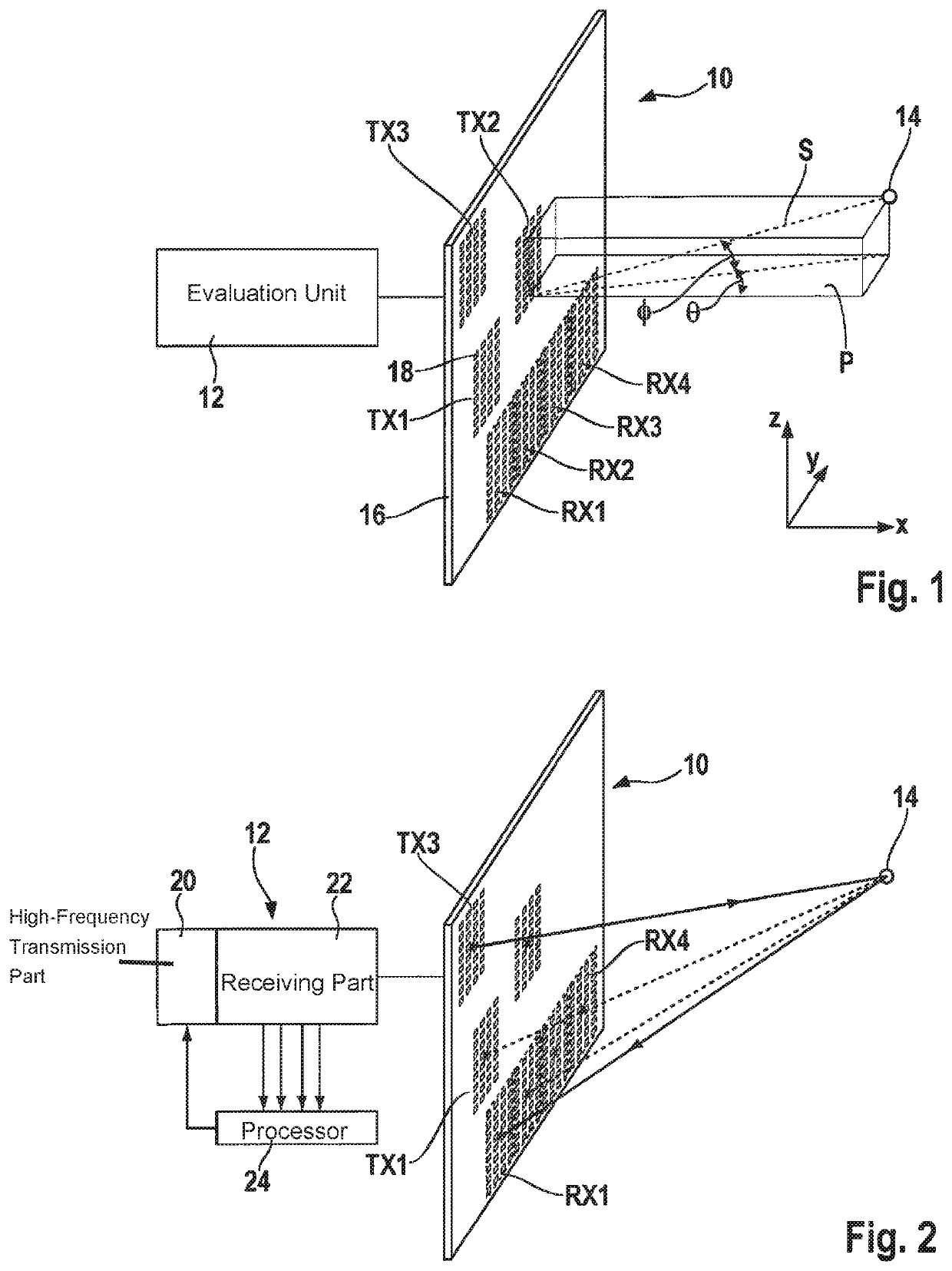
[0022]FIG. 1 shows an antenna array 10 and a control and evaluation unit 12 of a radar sensor, which is used to measure distances, relative speeds as well as direction angles of objects. A single object 14 is shown here as an example. The radar sensor is, for example, installed in the front end of a motor vehicle not shown and is used, in particular, to detect preceding vehicles or other objects ahead of the vehicle.

[0023]The radar sensor shown here is designed specifically for a two-dimensional angle estimation, in which both azimuth angle θ as well as elevation angle ϕ of object 14 is estimated. Elevation angle ϕ in this case is defined as the angle between line of sight S from the center of the radar sensor to object 14 and an azimuthal (horizontal) plane P, which is spanned by a forward direction x of the vehicle and a sideward direction y (first direction y). Azimuth angle θ is defined as the angle between forward direction x and the vertical projection of line of sight S on az...


PUM


Abstract

A MIMO radar sensor is described for motor vehicles as including an antenna array, which is angle-resolving in two directions perpendicular to each other and including multiple receiving antennas, which are situated offset from one another in a first of the two directions, and multiple transmitting antennas, and including a control and evaluation unit for activating the transmitting antennas and for evaluating signals of the receiving antennas. The antenna array includes at least three selectively activatable transmitting antennas, which are offset from one another both in the first direction as well as in the second direction, and the control and evaluation unit is designed for a two-dimensional angle estimation in the first direction and the second direction using the signals received when the transmitting antennas are activated differently.

Description

FIELD OF THE INVENTION[0001]The present invention relates to a MIMO radar sensor for motor vehicles, including an antenna array, which is angle-resolving in two directions perpendicular to each other, and multiple receiving antennas arranged offset to one another in a first of the two directions, as well as multiple transmitting antennas, and a control and evaluation unit for activating the transmitting antennas and for evaluating the signals of the receiving antennas.BACKGROUND INFORMATION[0002]Radar sensors are employed in driver assistance systems or in autonomous vehicle guidance systems for motor vehicles for monitoring surroundings, in particular, for measuring distances, relative speeds and direction angles of other vehicles and also of stationary objects. In addition to detecting the azimuth angle of an object, i.e., the angle between the forward direction of the vehicle and the line of sight to the object in a horizontal plane, it is often also necessary to detect the eleva...

Claims


Application Information

Patent Timeline
Patent Type & Authority Patents(United States)
IPC IPC(8): G01S7/03G01S13/00G01S13/42G01S13/931H01Q1/32H01Q21/00G01S13/34
CPCG01S7/032G01S13/003G01S13/42G01S13/931H01Q1/3233H01Q21/0025G01S13/343G01S13/422H01Q3/24H01Q21/065H01Q21/28
Inventor LOESCH, BENEDIKTSCHOOR, MICHAEL
Owner ROBERT BOSCH GMBH
Why Eureka
Try Eureka