Pouch with flexible self-sealing dispensing valve

a self-sealing, pouch technology, applied in the field of pouches, can solve the problem of becoming more difficult to control the amount of low viscosity products exiting the pouch, and achieve the effect of increasing the viscosity of the product, reducing the risk of product leakage, and increasing the bending resistan

Active Publication Date: 2021-10-05
BEMIS COMPANY INC
View PDF86 Cites 1 Cited by
  • Summary
  • Abstract
  • Description
  • Claims
  • Application Information

AI Technical Summary

Benefits of technology

[0005]Surprisingly, it was discovered that this resilience or stiffness can be controlled more effectively by the combination of an orifice and a flexible self-sealing dispensing valve when each is superimposed over the other in the construction of the pouch. When a fluid product inside the pouch is urged against the combined orifice and valve by manually squeezing the pouch, the sections formed by the intersecting lines of weakness of the valve must bend outwardly to permit the product to flow out of the pouch. The orifice provides additional bending resistance to the sections of the valve and limits the amount of the fluid product passing through the valve. Typically, the higher the viscosity of the product, the more force is required to bend the flexible sections outwardly. Generally, it is easier to manually control larger amounts of force than smaller amounts of force. It becomes more difficult to control the amount of low viscosity products exiting the pouch because the valve sections require a relatively weak force to bend outwardly with these products. With the combined orifice and valve of the present invention, the amount of force required to bend valve sections can be augmented for low viscosity products. The bending force of the valve sections can be readily controlled for both low and high viscosity products by one or more of the following stiffness parameters: the material used to form the orifice, the thickness of the material and the size of the orifice, and the material used to form the valve and its thickness, and the size of valve sections formed by the at least two lines of weakness. When the force used to deflect the valve sections is removed, the sections return to their original position and close the opening in the pouch.
[0006]Thus, the present invention advantageously provides a pouch having a means to manually discharge a fluid product from inside the pouch that can be tailored to permit its use with products of various viscosities. The option of configuring the means to manually discharge a fluid by either: (i) an orifice formed in one of the first or second wall portions and a flexible self-sealing dispensing valve formed in the patch which is superimposed over the orifice: or (ii) a flexible self-sealing dispensing valve formed in one of the first or second wall portions and an orifice formed in the patch with the patch superimposed over the flexible self-sealing dispensing valve adds more flexibility to adjust the stiffness parameters to meet the needs of a particular desired application.

Problems solved by technology

It becomes more difficult to control the amount of low viscosity products exiting the pouch because the valve sections require a relatively weak force to bend outwardly with these products.

Method used


Image

  • Pouch with flexible self-sealing dispensing valve
  • Pouch with flexible self-sealing dispensing valve
  • Pouch with flexible self-sealing dispensing valve

Examples


Embodiment Construction

[0024]The present inventions now will be described more fully hereinafter with reference to the accompanying drawings, in which some, but not all embodiments of the inventions are shown. Indeed, these inventions may be embodied in many different forms and should not be construed as limited to the embodiments set forth herein; rather, these embodiments are provided so that this disclosure will satisfy applicable legal requirements. Like numbers refer to like elements throughout.

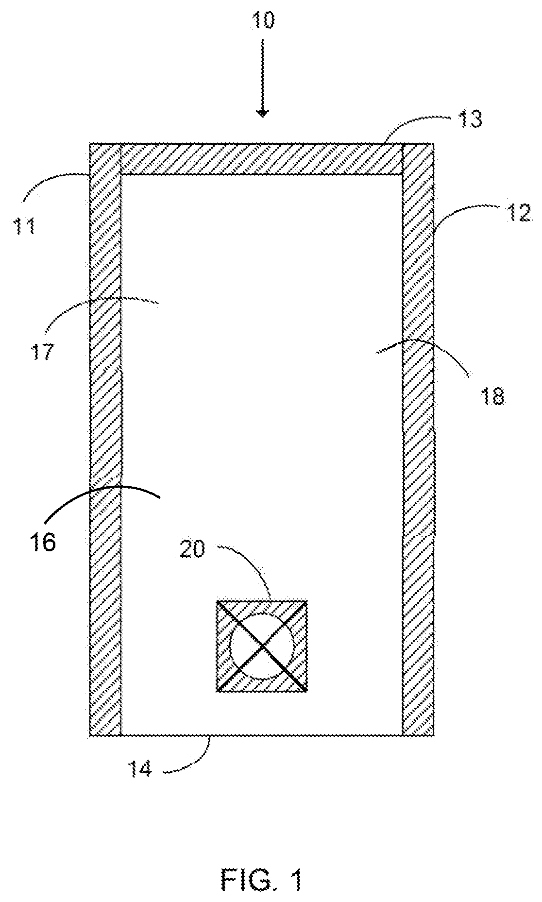
[0025]One preferred embodiment of flexible fluid-dispensing pouch 10 of the present invention is illustrated in FIG. 1. In this particular embodiment, pouch 10 is configured as a pillow pouch. It should be understood that pouch 10 may be of any shape desired, such as, for example, rectangular, square, and circular or polygon and may have any internal volume depending on both functional and aesthetic requirements of a particular packaging application. Generally, pouch 10 includes at least a first side edge 11, ...


PUM

PropertyMeasurementUnit
total thicknessaaaaaaaaaa

Abstract

The present invention is directed to fluid-dispensing flexible pouches having at least a first wall portion, a second wall portion and a means to manually discharge a fluid product from inside the pouch. The means to manually discharge a fluid from inside the pouch comprises an orifice formed in either one of the first or second wall portions or a patch, and a flexible self-sealing dispensing valve having at least two intersecting lines of weakness formed in either one of the first or second wall portions or the patch.

Description

BACKGROUND OF THE INVENTION[0001]The present invention relates generally to primary packaging for fluid or viscous products and the like, and in particular to pouches having a flexible self-sealing dispensing valve.[0002]Many different types of packages or containers are presently available for packaging non-solid products of the type which are capable of flowing, such as fluid or fluidized materials, including liquids, pastes, powders, and the like, which substances are collectively and generically referred to herein as “fluids”. Fluid material also includes viscous food products like pancake batter, syrups and various types of condiments that include mayonnaise, guacamole, ketchup and mustard. Such foods are often provided to restaurants and food service providers in rigid or flexible plastic tubes. Some such packages include a dispenser which permits a selected amount of fluid to be discharged from the package, and then reseals to close the package. Typically, these self-sealing ...

Claims


Application Information

Patent Timeline
Patent Type & Authority Patents(United States)
IPC IPC(8): B65D35/46B65D35/04B65D35/10B65D75/58B65D75/00
CPCB65D35/46B65D35/04B65D35/10B65D75/008B65D75/5877B65D75/5894
Inventor HOLMI, HANNA MTRACY, JORDAN RSCHNABEL, DONALD C
Owner BEMIS COMPANY INC
Why Eureka
Try Eureka