Rotary damper

a rotary damper and damping technology, applied in the direction of shock absorbers, movable seats, transportation and packaging, etc., can solve the problems of generating a small damping torque and a large damping torque, and achieve the effect of generating a small damping torque and no large damping torqu

Active Publication Date: 2021-10-12
OILES CORP
View PDF18 Cites 0 Cited by
  • Summary
  • Abstract
  • Description
  • Claims
  • Application Information

AI Technical Summary

Benefits of technology

[0019]In the present invention, the bypass passage including the groove longer than the thickness of the vane in the rotational direction of the rotor, is located on one or both of the bottom side or the inner peripheral surface side of the circular cylindrical chamber and / or on the lower side of the lid; while the surfaces at both end of the vane in the rotational direction of the rotor are located inside the bypass passage, the area upstream and the area downstream from the vane against the rotational direction of the rotor are communicated to each other through the bypass passage and the viscous fluid in these area upstream and the area downstream become movable through the bypass passage, resulting in generation of no large damping torque in relation to a rotating force on the rotor. Conversely, while at least one of the surfaces forming both ends of the vane in the rotational direction of the rotor are located outside the bypass passage, the bypass passage provides no communication between the areas upstream and downstream from the vane against the rotational direction of the rotor and the viscous fluid in these areas becomes immovable through the bypass passage, resulting in generation of a large damping torque in relation to a rotating force on the rotor. Consequently, changing a length and a position of the groove included in the bypass passage allows for optional setting a timing when a damping torque generates in relation to a rotating force on the rotor.

Problems solved by technology

This results in generating a large damping torque with the start of rotating the rotor in the forward direction.
This results in generating a small damping torque with the start of rotating the rotor in the backward direction.

Method used


Image

  • Rotary damper
  • Rotary damper
  • Rotary damper

Examples


Embodiment Construction

[0031]In the following, one embodiment of the present invention will be described with reference to the drawings.

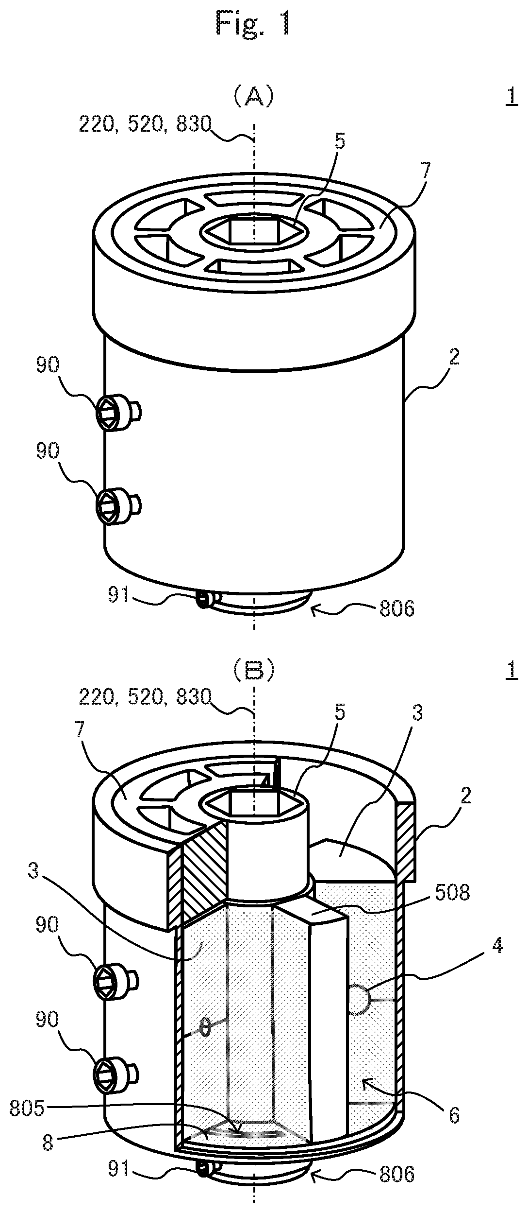
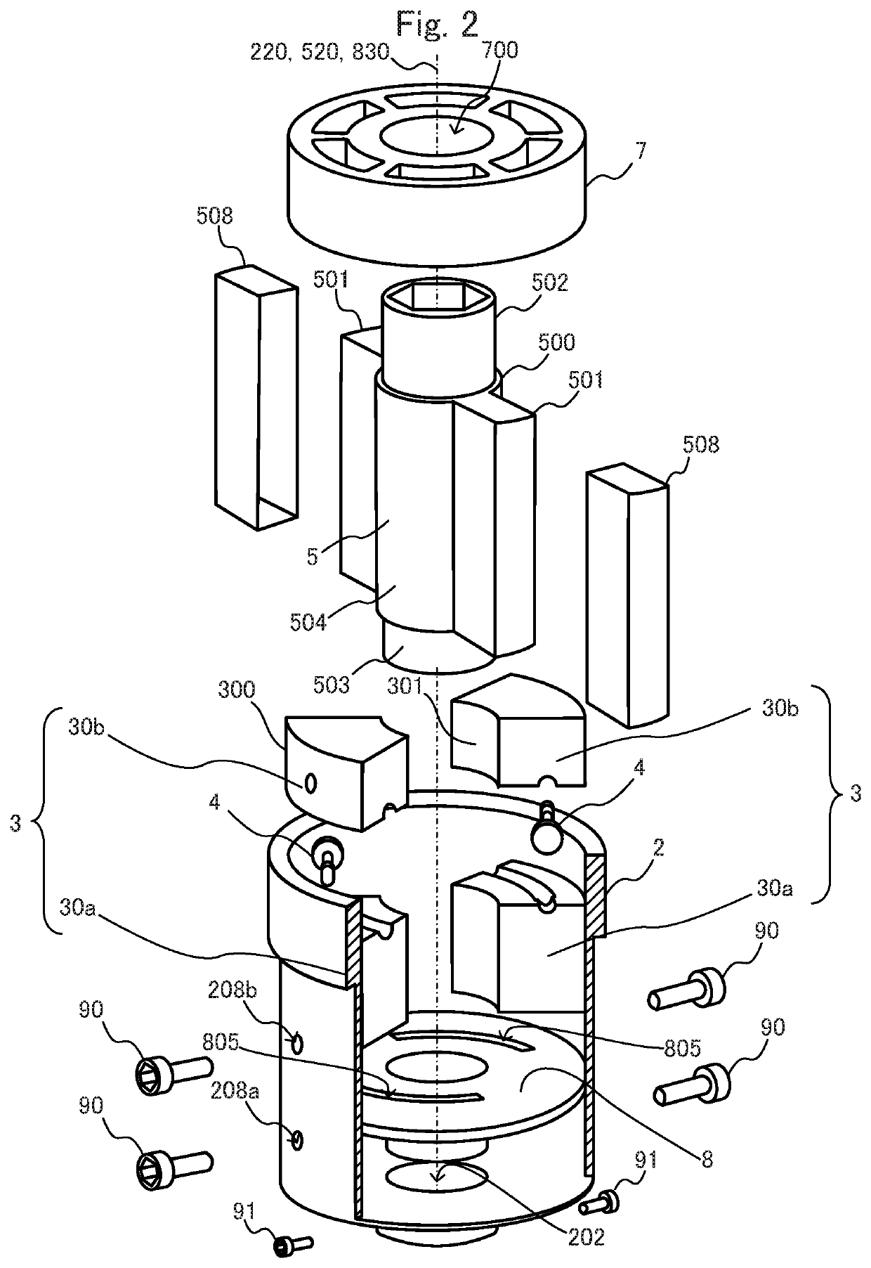
[0032]FIG. 1(A) and FIG. 1(B) are respectively an external view and a partial cross sectional view, each illustrating a schematic configuration of a rotary damper 1 according to the present embodiment. FIG. 2 is an illustrated parts breakdown of the rotary damper 1 according to the present embodiment.

[0033]As illustrated in the figures, the rotary damper 1 according to the present embodiment includes a casing 2; a pair of partitions 3; a pair of check valves 4; a rotor 5; viscous fluid 6 filled in the casing 2, such as oil and silicone; a lid 7; and a torque regulation plate 8.

[0034]The casing 2 contains the pair of the partitions 3 to each of which the check valve 4 is attached, the rotor 5, and the torque regulation plate 8, along with the viscous fluid 6.

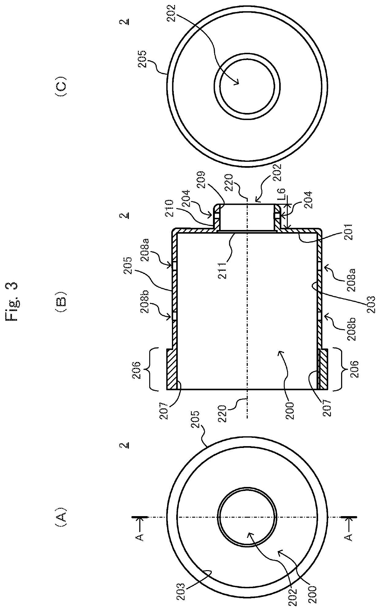
[0035]FIG. 3(A) is a front view of the casing 2, FIG. 3(B) is an A-A cross sectional view of the casing 2 illustrate...


PUM


Abstract

Provided is a rotary damper on which the timing for generating a damping torque can be set freely. Groove-like bypass passages (805) that are longer in the circumferential direction than vanes (501) are formed in the upper surface (803) of a torque regulation plate (8) arranged on the bottom part (201) of a cylindrical circular chamber (200). When the rotor (5) rotates in a first rotational direction R1, if both end faces (508a, 508b) of the vanes (501) are positioned within a range of the respective bypass passages (805), each area (218) and the corresponding area (217) are communicated via the corresponding bypass passage (805), enabling movement of a viscous fluid (6) from the area (217) to the area (218). Subsequently, if the rotor (5) rotates further in the first rotational direction R1 and one or both of the end faces (508a, 508b) of each vane (501) is outside of the range of the corresponding bypass passage (805), each area (218) and the corresponding area (217) are not communicated via the corresponding bypass passage (805), and the viscous fluid (6) is unable to move from each area (217) to the corresponding area (218).

Description

[0001]This application is the U.S. national phase of International Application No. PCT / JP2018 / 009557 filed 12 Mar. 2018, which designated the U.S. and claims priority to JP Patent Application No. 2017-050362 filed 15 Mar. 2017, the entire contents of each of which are hereby incorporated by reference.TECHNICAL FIELD[0002]The present invention relates to a rotary damper, and in particular relates to a rotary damper with settable timing for generation of a damping torque.BACKGROUND ART[0003]A known damper generates a damping torque in reaction to applied rotating force. For example, the Patent Literature 1 discloses so-called uni-directional rotary damper capable of generating a large damping torque in relation to a rotation in a forward direction, whereas a small damping torque in relation to a rotation in a backward direction.[0004]The rotary damper described in the Patent Literature 1 includes a casing having a circular cylindrical chamber, a rotor rotatably contained in the circul...

Claims


Application Information

Patent Timeline
Patent Type & Authority Patents(United States)
IPC IPC(8): F16F9/14B60N2/02F16F9/34F16F9/44F16F9/48
CPCF16F9/14F16F9/34B60G2202/22E05Y2201/256F16F9/44F16F9/48F16F9/145F16F9/346
Inventor KANEKO, RYOHEI
Owner OILES CORP
Why Eureka
Try Eureka