Supercharge Your Innovation With Domain-Expert AI Agents!

Wavelength converter, light source apparatus, and projector

a technology of light source apparatus and wavelength converter, which is applied in the direction of picture reproducers, picture reproducers using projection devices, instruments, etc., can solve the problems of reducing fluorescence use efficiency and light use efficiency of illumination apparatuses

Active Publication Date: 2021-10-26
SEIKO EPSON CORP
View PDF11 Cites 0 Cited by
  • Summary
  • Abstract
  • Description
  • Claims
  • Application Information

AI Technical Summary

Benefits of technology

[0005]A wavelength converter according to an aspect of the present disclosure includes a wavelength conversion layer that has a first surface and a second surface different from the first surface and converts excitation light that belongs to a first wavelength band into fluorescence that belongs to a second wavelength band different from the first wavelength band, a first light transmissive member that has a third surface on which the excitation light is incident and a fourth surface different from the third surface and transmits at least the excitation light, and a first layer provided between the first surface of the wavelength conversion layer and the fourth surface of the first light transmissive member, which are surfaces facing each other. A refractive index of the first light transmissive member is greater than a refractive index of the wavelength conversion layer, and the first layer transmits the excitation light and reflects the fluorescence.

Problems solved by technology

The illumination apparatus therefore has a problem of a decrease in fluorescence use efficiency.
Further, the fluorescence produced in the phosphor layer has a Lambert light orientation distribution, which means a large etendue, resulting in a problem of a decrease in the light use efficiency.

Method used


Image

  • Wavelength converter, light source apparatus, and projector
  • Wavelength converter, light source apparatus, and projector
  • Wavelength converter, light source apparatus, and projector

Examples


first embodiment

[0033]A first embodiment of the present disclosure will be described below with reference to FIGS. 1 to 4.

[0034]In the following drawings, components are drawn at different dimensional scales in some cases for clarity of each of the components.

[0035]An example of a projector according to the present embodiment will be descried.

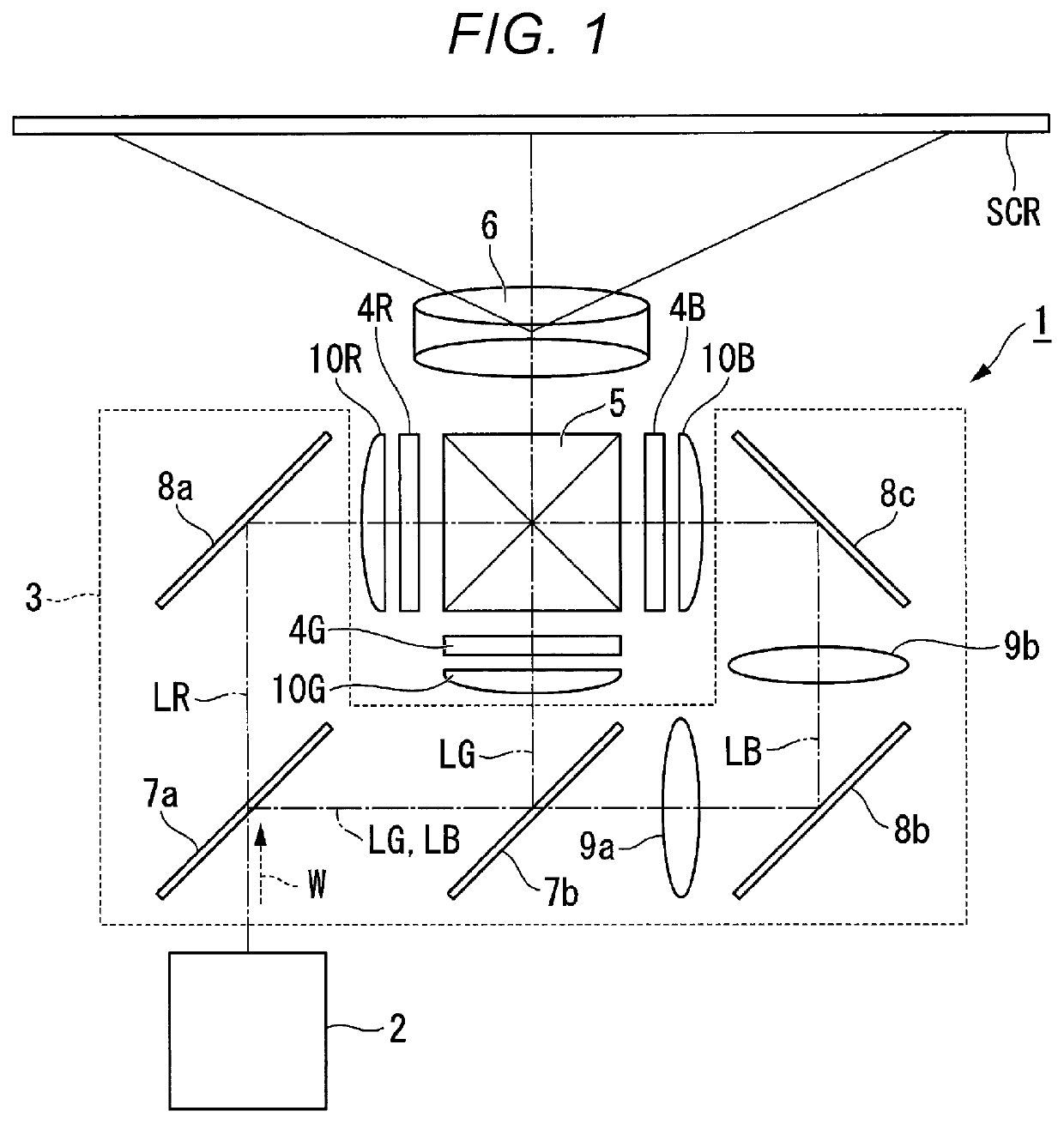
[0036]FIG. 1 shows a schematic configuration of a projector 1 according to the present embodiment.

[0037]The projector 1 according to the present embodiment is a projection-type image display apparatus that displays color video images on a screen SCR, as shown in FIG. 1. The projector 1 includes an illumination apparatus 2, a color separation system 3, a light modulator 4R, a light modulator 4G, a light modulator 4B, a light combining system 5, and a projection optical apparatus 6. The configuration of the illumination apparatus 2 will be described later.

[0038]The color separation system 3 includes a first dichroic mirror 7a, a second dichroic mirror 7b, a refl...

second embodiment

[0099]A second embodiment of the present disclosure will be described below with reference to FIG. 5.

[0100]The configurations of a projector and a light source apparatus according to the second embodiment are the same as those in the first embodiment, and the configuration of the wavelength converter differs from that in the first embodiment. No description of the projector or the light source apparatus will therefore be made.

[0101]FIG. 5 is a cross-sectional view of a wavelength converter 60 according to the second embodiment.

[0102]In FIG. 5, components common to those in the figures used in the description of the first embodiment have the same reference characters and will not be described.

[0103]The wavelength converter 60 includes the first heat dissipation member 51, the wavelength conversion layer 52, the first light transmissive member 53, the first dichroic mirror 54 (first layer), a second dichroic mirror 61 (second layer), and the reflection layer 55, as shown in FIG. 5. Th...

third embodiment

[0109]A third embodiment of the present disclosure will be described below with reference to FIG. 6.

[0110]The configurations of a projector and a light source apparatus according to the third embodiment are the same as those in the first embodiment, and the configuration of the wavelength converter differs from that in the first embodiment. No description of the projector or the light source apparatus will therefore be made.

[0111]FIG. 6 is a cross-sectional view of a wavelength converter 64 according to the third embodiment.

[0112]In FIG. 6, components common to those in the figures used in the description of the aforementioned embodiments have the same reference characters and will not be described.

[0113]The wavelength converter 64 includes the first heat dissipation member 51, the wavelength conversion layer 52, the first light transmissive member 53, the first dichroic mirror 54 (first layer), the second dichroic mirror 61 (second layer), a second heat dissipation member 65, and t...


PUM

PropertyMeasurementUnit
angle of incidenceaaaaaaaaaa
peak wavelengthaaaaaaaaaa

Abstract

A wavelength converter according to the present disclosure includes a wavelength conversion layer that has a first surface and a second surface different from the first surface and converts excitation light that belongs to a first wavelength band into fluorescence that belongs to a second wavelength band different from the first wavelength band, a first light transmissive member that has a third surface on which the excitation light is incident and a fourth surface different from the third surface and transmits at least the excitation light, and a first layer provided between the first surface of the wavelength conversion layer and the fourth surface of the first light transmissive member, which are surfaces facing each other. The refractive index of the first light transmissive member is greater than the refractive index of the wavelength conversion layer, and the first layer transmits the excitation light and reflects the fluorescence.

Description

[0001]The present application is based on, and claims priority from JP application Serial Number 2019-116916, filed Jun. 25, 2019, the disclosure of which is hereby incorporated by reference herein in its entirety.BACKGROUND1. Technical Field[0002]The present disclosure relates to a wavelength converter, a light source apparatus, and a projector.2. Related Art[0003]As a light source apparatus used in a projector, there has been a proposed light source apparatus that uses fluorescence emitted from a phosphor irradiated with excitation light outputted from a light source. WO 2018 / 056157 discloses an illumination apparatus including a first substrate and a second substrate that transmit light, a phosphor layer provided between the first substrate and the second substrate, and a heat dissipation plate so provided as to be in contact with the first and second substrates.[0004]In the illumination apparatus described in WO 2018 / 056157, part of fluorescence produced in the phosphor layer en...

Claims


Application Information

Patent Timeline
Patent Type & Authority Patents(United States)
IPC IPC(8): G03B21/20H04N9/31H01L33/50
CPCG03B21/204G03B21/2013G03B21/2066H01L33/501H04N9/3161H04N9/3164H04N9/3158H04N9/3144H01L33/507G03B21/20G03B21/2033G03B21/16
Inventor YASUMATSU, WATARUARAKAWA, OSAMUYOKOO, TOMOHIRO
Owner SEIKO EPSON CORP
Features
  • R&D
  • Intellectual Property
  • Life Sciences
  • Materials
  • Tech Scout
  • Unparalleled Data Quality
  • Higher Quality Content
  • 60% Fewer Hallucinations
Learn More