Color conversion processor, control method thereof and storage medium
a color conversion and processor technology, applied in the direction of cathode-ray tube indicators, static indicating devices, instruments, etc., can solve problems such as increasing computation costs, and achieve the effect of reducing computation costs for color conversion processing
- Summary
- Abstract
- Description
- Claims
- Application Information
AI Technical Summary
Benefits of technology
Problems solved by technology
Method used
Image
Examples
embodiment 1
(Hardware Configuration Example of Color Conversion Processor)
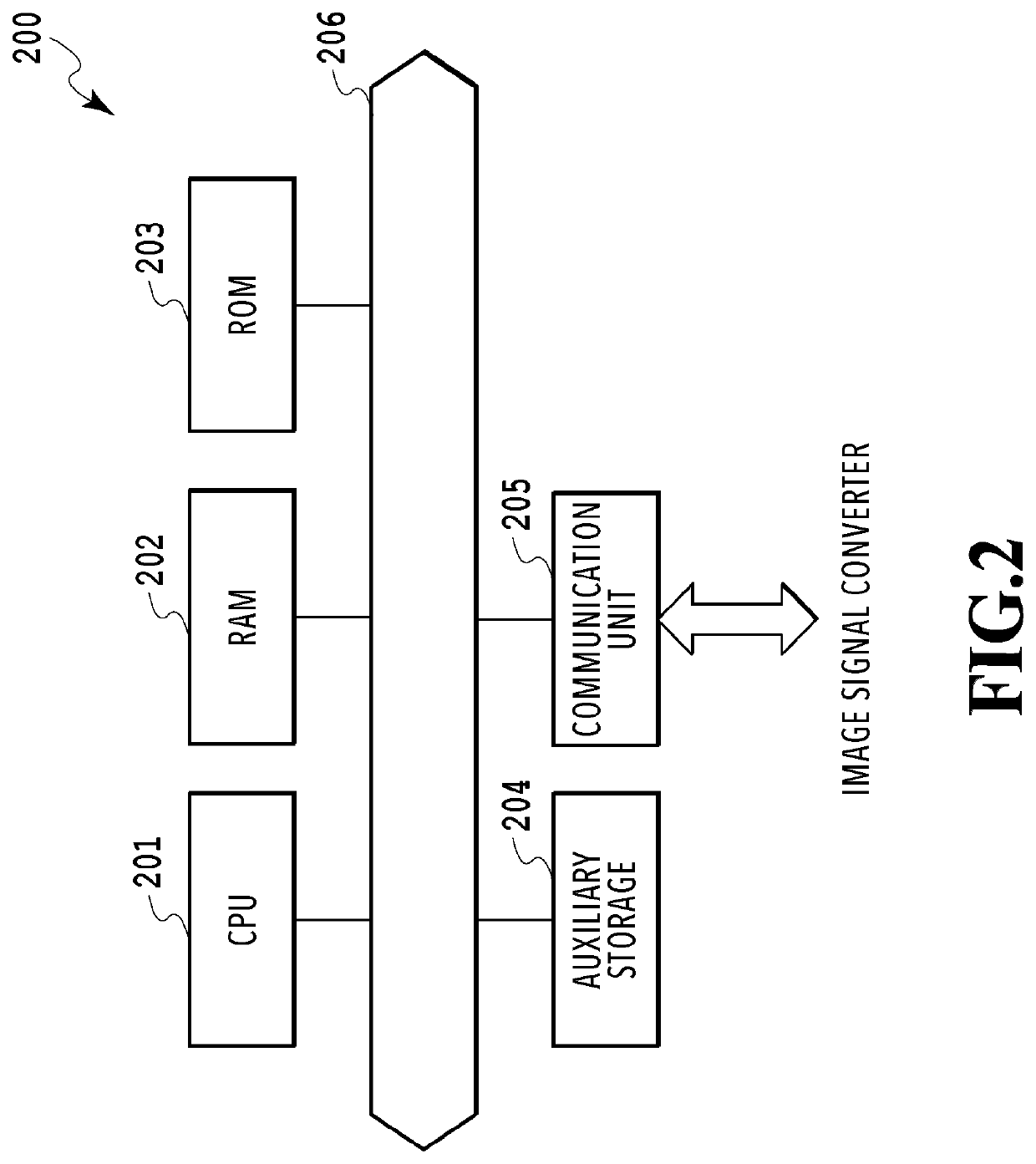
[0026]FIG. 2 is a block diagram that illustrates a hardware configuration example of the color conversion processor 200 of this embodiment. The color conversion processor 200 includes a CPU 201, a RAM 202, a ROM 203, an auxiliary storage 204, and a communication unit 205, and these are communicably connected with each other via an interconnector 206. The CPU 201 is formed of an arithmetic circuit and controls the entirety of the color conversion processor 200. The CPU 201 reads a program stored in the ROM 203 out to the RAM 202 and executes various kinds of processing. The ROM 203 stores system software and the like used for controlling the color conversion processor 200. The auxiliary storage 204 has a function of a storage region. The communication unit 205 mainly communicates with the image signal converter 10 under control of the CPU 201. In this embodiment, an example in which the color conversion processor 200 is a ...
embodiment 2
[0054]In this embodiment, an example in which the linear function approximation is applied for simplifying the computation according to Equation 4 in the luminance correction value derivation (S404) is described. Descriptions of the parts common to Embodiment 1 are simplified or omitted, and unique points of this embodiment are mainly described below.
[0055]In this embodiment, a specific example of a computing equation for obtaining a linear function approximation value is expressed by Equation 6:
ALPHAdata14=ALPHAa·(−MINdata12)+ALPHAb. (Equation 6)
[0056]ALPHAa and ALPHAb are coefficients used for obtaining the linear function approximation value. FIG. 6B illustrates comparison of a theoretical value obtained by the computation according to Equation 3 and approximation values obtained by the computation according to Equation 6. FIG. 6B is a graph that illustrates a relationship of the minimum value 12 and the luminance correction value 14 while the horizontal axis is the minimum valu...
embodiment 3
[0059]In this embodiment, an example in which a color matching capability is adjusted by revising the value of the minimum value 12. Descriptions of the parts common to Embodiment 1 are simplified or omitted, and unique points of this embodiment are mainly described below.
[0060]In S402, the minimum value extraction unit 212 extracts the negative minimum color component value from the RGB data in the provisional color-converted data 11. Then, the minimum value extraction unit 212 multiplies the extracted minimum value by minimum value gain and outputs the value obtained by the multiplication as the minimum value 12. For example, when the color conversion input data 2 is the pure color of G and the minimum value gain is 0.5, MINdata12=−0.588×0.5=−0.294. If no negative value is in the provisional color-converted data 11, the minimum value 12 is set as MINdata12=0, and processing of S403 to S404 may be skipped.
[0061]When the minimum value gain is 0.5, the color-corrected data 13, the lu...
PUM
 Abstract
Description
Claims
Application Information
 - R&D
- Intellectual Property
- Life Sciences
- Materials
- Tech Scout
- Unparalleled Data Quality
- Higher Quality Content
- 60% Fewer Hallucinations
Browse by: Latest US Patents, China's latest patents, Technical Efficacy Thesaurus, Application Domain, Technology Topic, Popular Technical Reports.
© 2025 PatSnap. All rights reserved.Legal|Privacy policy|Modern Slavery Act Transparency Statement|Sitemap|About US| Contact US: help@patsnap.com


