
Image display system

a display system and image technology, applied in the field of image display systems, can solve the problems of affecting the brightness of transmission images transmitted through the transmissive display device and displayed, and affecting the viewing of superimposed images

Active Publication Date: 2021-11-02
FUJIFILM CORP
View PDF8 Cites 0 Cited by
  • Summary
  • Abstract
  • Description
  • Claims
  • Application Information

AI Technical Summary

Benefits of technology

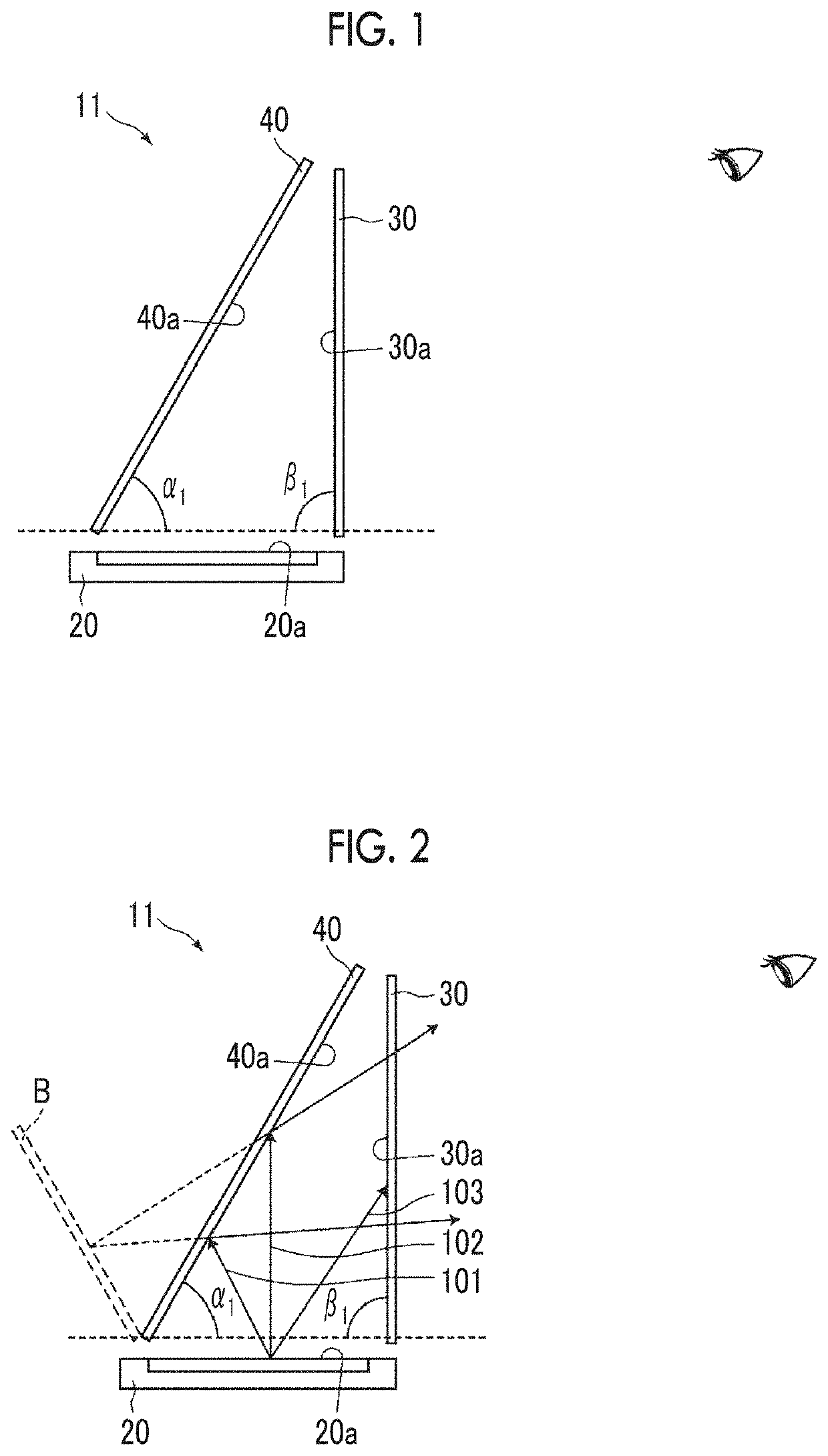
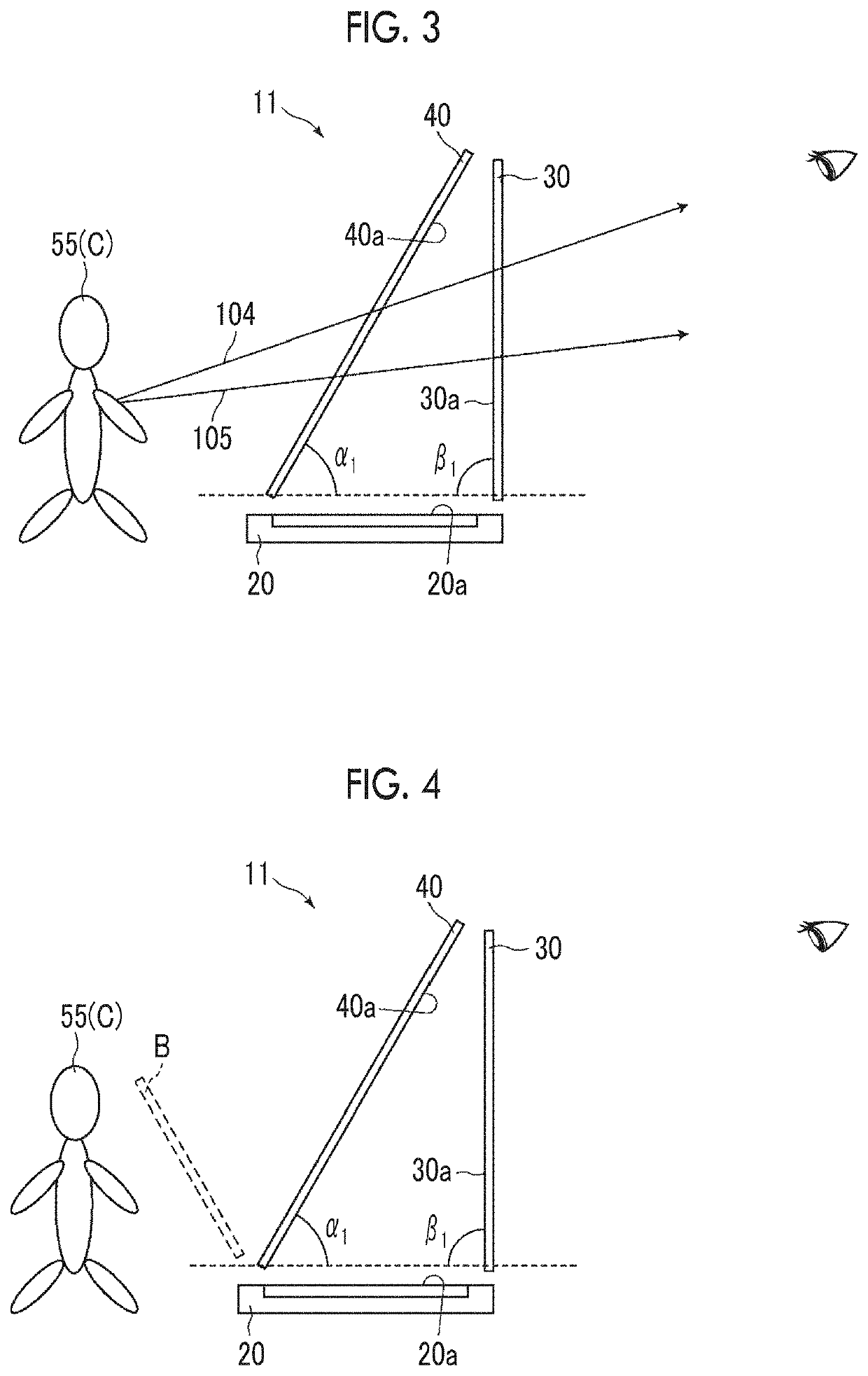
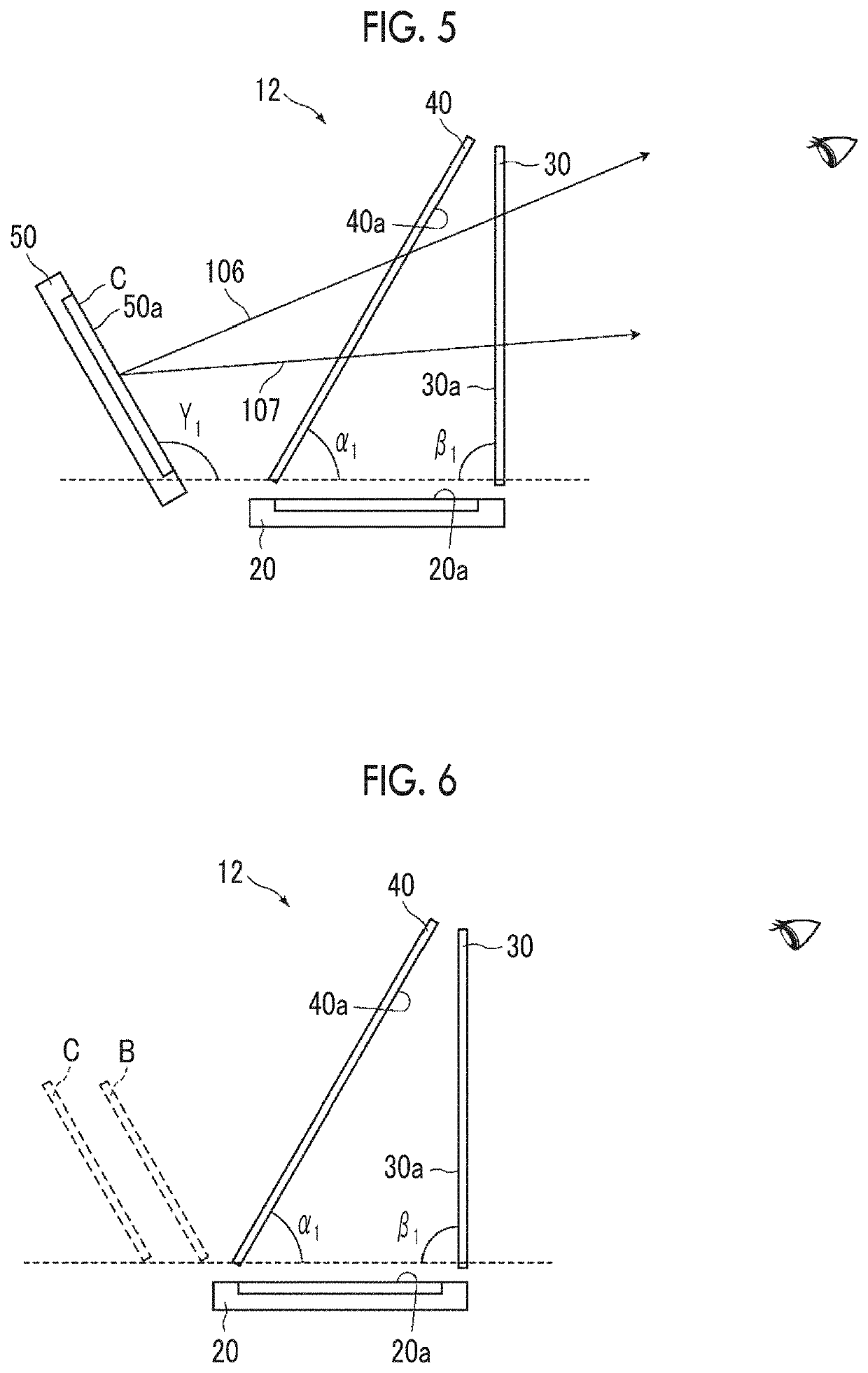
[0012]The invention has been accomplished in consideration of the above-described problem, and an object of the invention is to provide an image display system capable of displaying a high-brightness superimposed image with space saving without restraining a direct image disturbing watching of the superimposed image from being viewed.
[0035]According to the invention, it is possible to provide an image display system capable of displaying a high-brightness superimposed image with space saving without restraining a direct image disturbing watching of the superimposed image from being viewed.

Problems solved by technology

According to the above-described Pepper's ghost and the display method described in JP2015-210379A, since the first image display unit 220 is provided on a viewing side from the beam splitter 230, there is a problem in that an image displayed on the first image display unit 220 is directly viewed and disturbs watching of a superimposed image.
According to the method using the transmissive display device described in JP3460671B, there is a problem in that the transmittance of the transmissive display device is generally low, and brightness of a transmission image transmitted through the transmissive display device and displayed significantly decreases.
According to the method using the transmissive screen described in JP2011-076121A, there is a problem in that a projector that projects an image onto the transmissive screen is needed, the system increases in size, and an installation place is limited.

Method used


Image

  • Image display system
  • Image display system
  • Image display system

Examples


example 1

[0202]Example 1 is a specific configuration example of the first image display system of the invention. FIG. 21 shows the schematic configuration of Example 1.

[0203]A tablet terminal Kindle fire HDX manufactured by Amazon.com, Inc. was provided such that an image display surface 20a turned upward, thereby obtaining the first image display unit 20 (hereinafter, a surface on which the first image display unit 20 is provided is referred to as a “bottom surface”). Light emitted from Kindle fire HDX was linearly polarized light (first polarized light).

[0204]Next, the absorption polarizer 21 was provided on the image display surface 20a of the first image display unit 20 such that the transmission axis became a direction to transmit linearly polarized light emitted from the first image display unit 20.

[0205]Next, the absorption polarizer 30 was provided such that an angle to the image display surface 20a of the first image display unit 20 became 90° at a position on the viewing side from ...

example 3

[0215]FIG. 23 shows the schematic configuration of an image display system 83 of Example 3.

[0216]In the image display system 82 of Example 2, the absorption polarizer 121 was provided on the image display surface 120a of the first image display unit 120 such that the transmission axis was in a direction to transmit linearly polarized light emitted from the first image display unit 120.

[0217]In this way, the image display system 83 of Example 3 was produced.

example 4

[0218]FIG. 24 shows the schematic configuration of an image display system 84 of Example 4.

[0219]In the image display system 83 of Example 3, the half mirror 72 with a quarter-wave retardation plate was used as the beam splitter 140, and was provided such that the slow axis of the quarter-wave retardation film 63 was in a direction of 45° to the transmission axis of the reflective polarizer 130 in a case of being viewed from the viewing side.

[0220]In this way, the image display system 84 of Example 4 was produced.


PUM

PropertyMeasurementUnit
wavelengthaaaaaaaaaa
angle β2aaaaaaaaaa

Abstract

An image display system includes a first image display unit that has a first image display surface for displaying a first image and emits first emission light as first polarized light, a beam splitter that has a transflective surface for transmitting a part of incident light and reflecting another part of the incident light, the transflective surface being arranged at a position where the first emission light emitted from the first image display unit is incident, and the beam splitter changing the polarized light of the first emission light and reflecting the first emission light, and an absorption polarizer that is arranged at a position where reflected light reflected from the transflective surface of the beam splitter out of the first emission light is incident, to absorb the first polarized light and transmit second polarized light different from the first polarized light.

Description

CROSS-REFERENCE TO RELATED APPLICATIONS[0001]This application is a continuation application of International Application No. PCT / JP2018 / 010336, filed Mar. 15, 2018, which was published under Article 21(2) in Japanese, and which claims priority under 35 U.S.C. § 119(a) to Japanese Patent Application No. 2017-052995, filed Mar. 17, 2017. The above applications are hereby expressly incorporated by reference, in their entirety, into the present application.BACKGROUND OF THE INVENTION1. Field of the Invention[0002]The present invention relates to an image display system.2. Description of the Related Art[0003]In recent years, in an information display device or the like mounted in an automobile, the amount of information to be displayed increases, and it is difficult for a driver to identify information at first sight. Accordingly, in order to make information to be confirmed more conspicuous, it is desirable for a system that makes a display image to be confirmed float and be displayed i...

Claims


Application Information

Patent Timeline
Patent Type & Authority Patents(United States)
IPC IPC(8): G02B27/14G02B27/28G02B30/25
CPCG02B27/144G02B27/286G02B30/25G09F9/00G02B27/0101G02B27/283G02B30/56
Inventor YAMADA, NAOYOSHI
Owner FUJIFILM CORP
Learn More