
Optical touch display device and color filter thereof

a touch display device and color filter technology, applied in the direction of instruments, electric digital data processing, computing, etc., can solve the problem of difficulty in increasing the photo-sensing resolution of the conventional touch display device, and achieve the effect of good color performan

Active Publication Date: 2016-03-15
AU OPTRONICS CORP
View PDF22 Cites 0 Cited by
  • Summary
  • Abstract
  • Description
  • Claims
  • Application Information

AI Technical Summary

Benefits of technology

[0004]Therefore, the object of the present invention is to provide a color filter having a green photoresist with high light transmission for the light with long wavelength.
[0005]Another object of the present invention is to provide an optical touch display device including the above-mentioned color filter to display images with good color performance and high-brightness.

Problems solved by technology

However, according the current technique, there are only the red photoresists having the enough light transmittance with respect to the detecting light with long wavelength.
Accordingly, the amount of the light-detecting elements disposed in the conventional touch display device is limited by the arrangement of the light-detecting elements, so it is difficult to increase the photo-sensing resolution of the conventional touch display device.

Method used


Image

  • Optical touch display device and color filter thereof
  • Optical touch display device and color filter thereof
  • Optical touch display device and color filter thereof

Examples


Embodiment Construction

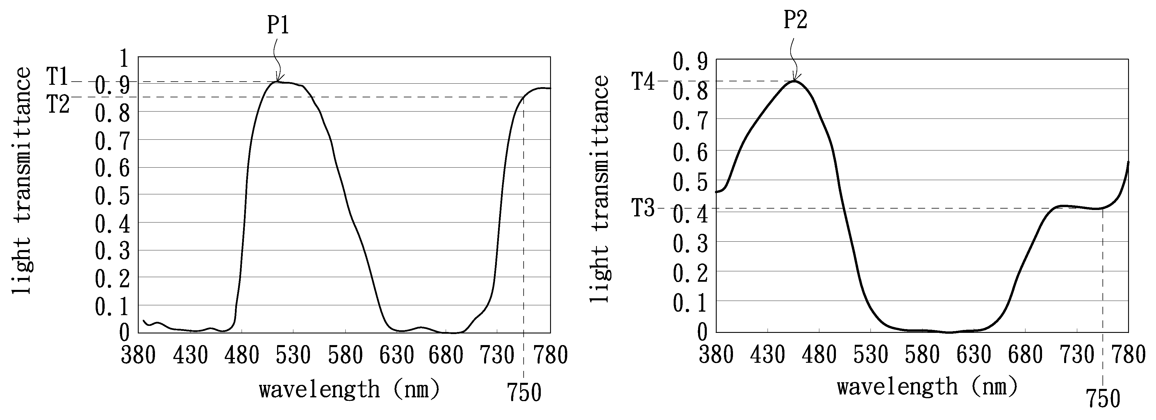
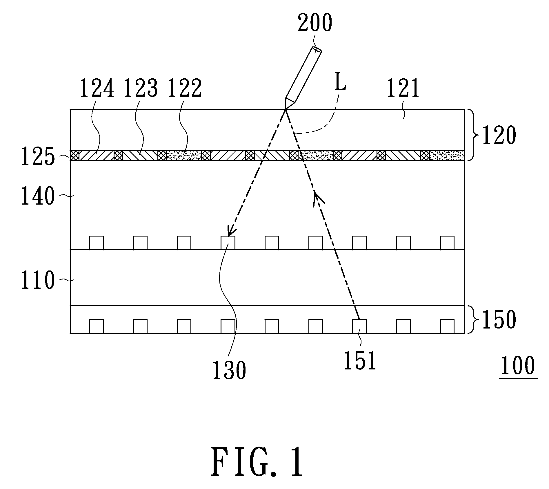
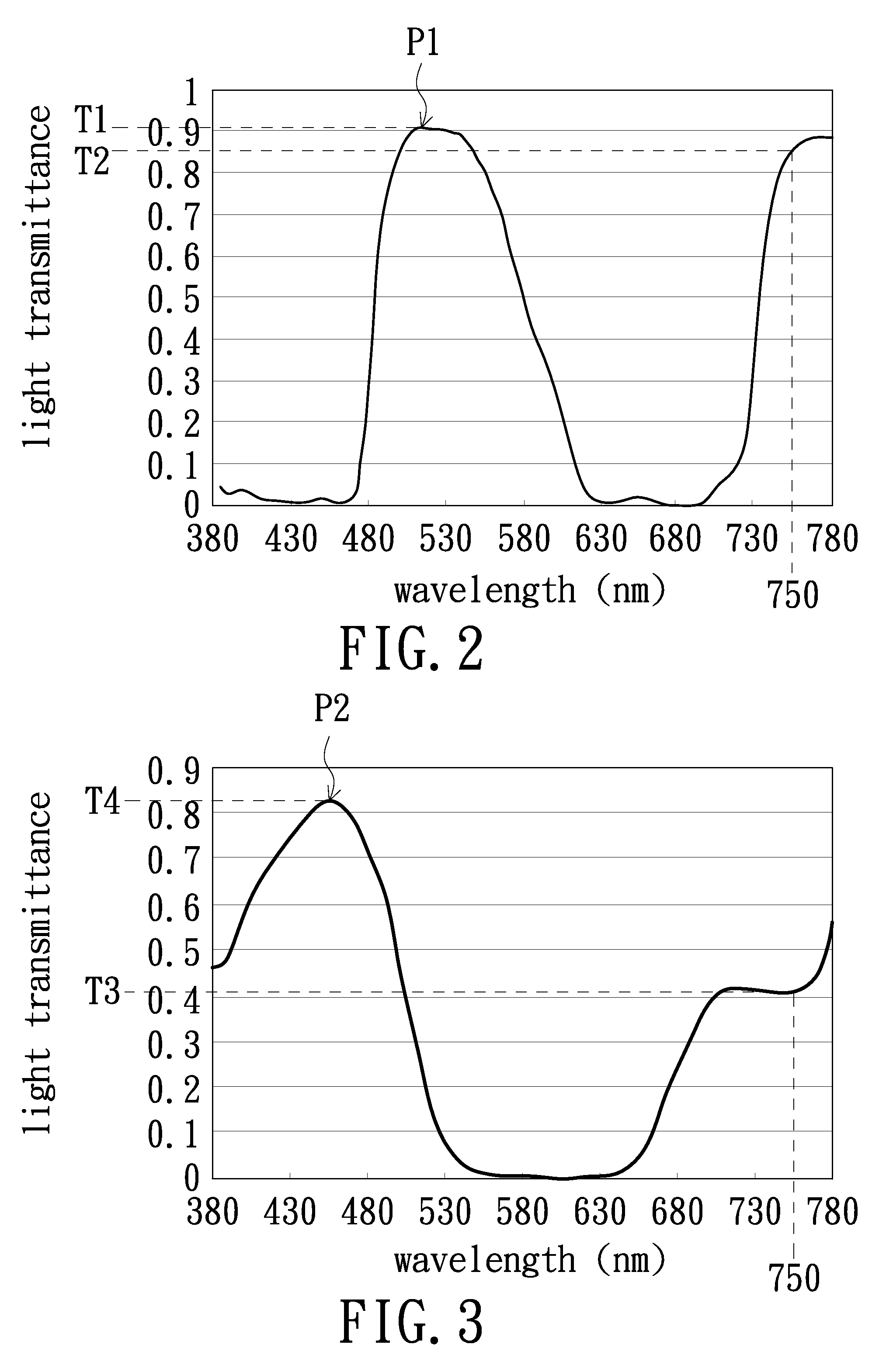
[0012]FIG. 1 is a cross-section view of the optical touch display device according to an embodiment of the invention, and FIG. 2 is a diagram illustrating a light transmitting spectrum function of the green photoresist shown in FIG. 1. Referring to FIG. 1 and FIG. 2, the optical touch display device 100 includes an active elements array substrate 110, a color filter 120, a plurality of light-detecting elements 130, a display medium layer 140 and a back light source 150. The color filter 120 is disposed above the active elements array substrate 110. Moreover, the color filter 120 includes a substrate 121 and a green photoresist 123 disposed on the substrate 121. In detail, the spectrum function of the green photoresist 123 has a first peak P1 within the wavelength window substantially between 480 nm and 550 nm, and a transmittance intensity T2 of the spectrum function of green photoresist 123 at wavelength 750 nm is substantially greater than that of 0.5 times of the transmittance in...


PUM

PropertyMeasurementUnit
wavelengthaaaaaaaaaa
wavelength windowaaaaaaaaaa

Abstract

A color filter including a substrate and a green photoresist is provided. The green photoresist is disposed on the substrate, and the spectrum function thereof has a first peak within a wavelength window between 480 nm and 550 nm. Whereas a transmittance intensity of the spectrum function of green photoresist at wavelength 750 nm is greater than that of 0.5 times of the transmittance intensity of the first peak. An optical touch display device with the color filter is also provided.

Description

TECHNICAL FIELD[0001]The present invention relates to an optical touch display device, and more particularly to an optical touch display device including a color filter.BACKGROUND[0002]With the progressing of the technology, the touch display device is widely used in electric products, such as tablet personal computer and smart phone. In the conventional touch display device, a light with long wavelength is used as detecting light, and a plurality of light-detecting elements are used for receiving the detecting light reflected from a touch operating element into the display device through a color filter. Generally, the color filter includes a plurality of red photoresists, a plurality of blue photoresists and a plurality of green photoresists. However, according the current technique, there are only the red photoresists having the enough light transmittance with respect to the detecting light with long wavelength. Therefore, in order to increase the light intensity received by the l...

Claims


Application Information

Patent Timeline
Patent Type & Authority Patents(United States)
IPC IPC(8): G02F1/1335G02B5/22G06F1/16G02B5/20G06F3/042
CPCG02B5/20G02B5/201G02B5/223G06F1/1692G06F3/042G02F1/133514G02F1/133516G09G3/3607G09G3/2003
Inventor CHEN, CHIEN-KAILI, CHIA-HAOLIAO, CHEN-HSIEN
Owner AU OPTRONICS CORP
Learn More