Circumferentially continuous and constrictable textile sleeve and method of construction thereof

a textile sleeve and circumferentially continuous technology, applied in the field of circumferentially continuous and constrictable textile sleeves, can solve the problems of limiting the type of protection cable provided by the wall, adding cost to the sleeve, etc., to and enhance the hoop strength and resistance to abrasion.

Active Publication Date: 2021-11-09
FEDERAL MOGUL POWERTAIN LLC
View PDF27 Cites 3 Cited by
  • Summary
  • Abstract
  • Description
  • Claims
  • Application Information

AI Technical Summary

Benefits of technology

[0009]In accordance with another aspect of the invention, the first section can include lengthwise extending warp multifilament yarns to enhance coverage protection and tenacity.
[0018]In accordance with another aspect of the invention, the method can further include forming the first section entirely of lengthwise extending warp multifilament yarns having a tenacity equal to or greater than 6.0 grams per denier (g / d) for enhanced mechanical protection and circumferentially extending, non-heat-shrinkable weft monofilament yarns having a diameter between 0.15-0.25 mm.

Problems solved by technology

Although the circumferentially continuous heat-shrinkable yarns function generally well to constrict the entirety of the seamless wall about the members being protected, they add cost to the sleeve as a result of being a relatively costly yarn, and further, limit the type of protection cable of being provided by the wall.

Method used


Image

  • Circumferentially continuous and constrictable textile sleeve and method of construction thereof
  • Circumferentially continuous and constrictable textile sleeve and method of construction thereof
  • Circumferentially continuous and constrictable textile sleeve and method of construction thereof

Examples


Embodiment Construction

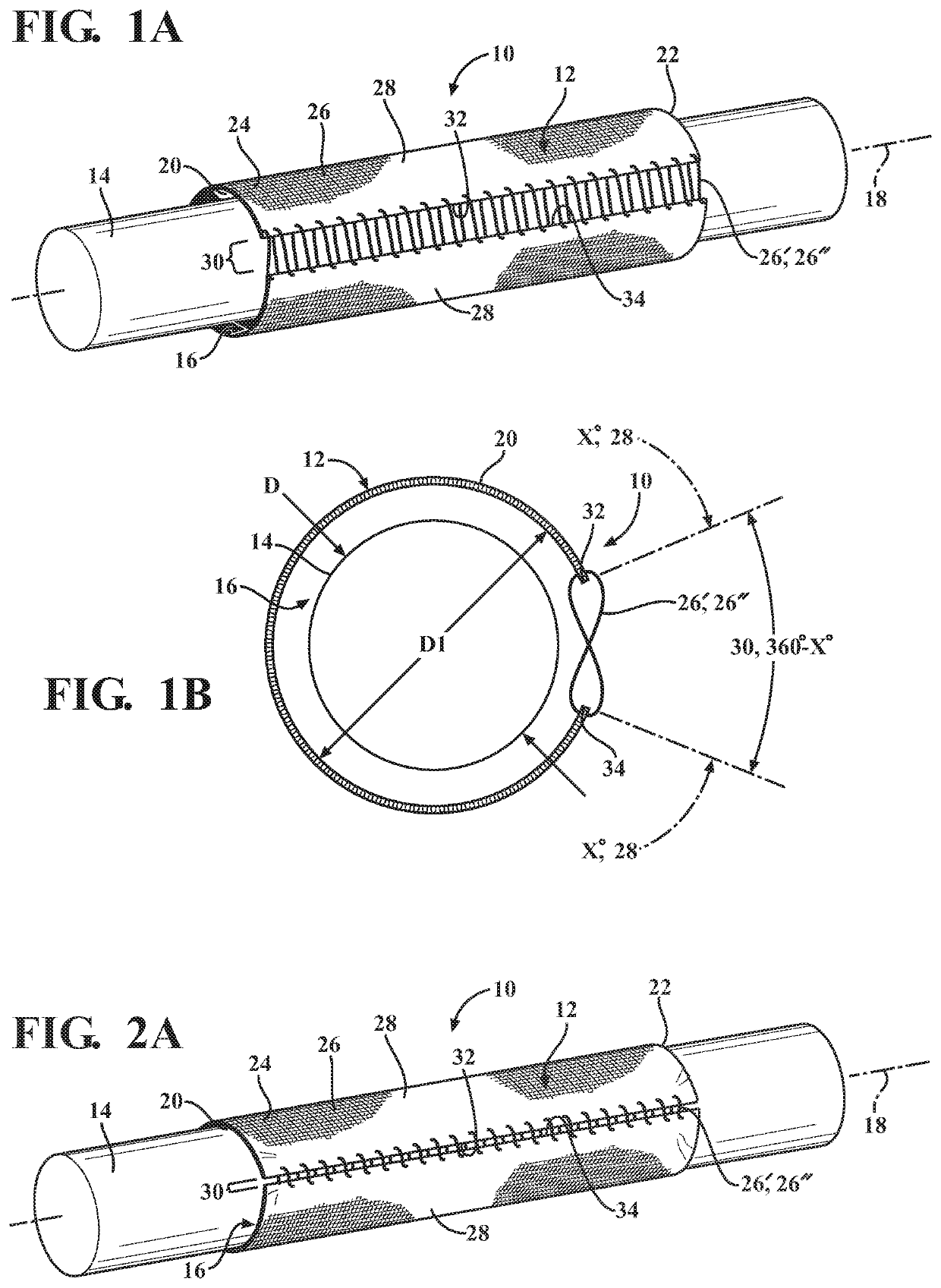
[0034]Referring in more detail to the drawings, FIG. 1A shows schematic representation of a textile sleeve, referred to hereafter as sleeve 10, having a circumferentially continuous wall 12 constructed in accordance with one aspect of the invention. Circumferentially continuous walls are sometimes referred to as “closed”, as they do not having lengthwise extending free edges, as opposed to “open” walls, which do. The sleeve 10 is used for routing and protecting elongate members 14 contained therein, such as conduits, wires, wires contained in sheaths or a bundled wire harness, for example, from exposure to environmental effects, such as abrasion and the ingress of contamination, debris and the like, by way of example and without limitation. The wall 12 bounds a central cavity 16 that extends along a longitudinal central axis 18 between opposite open ends 20, 22, wherein the elongate member 14 is disposed and contained in the cavity 16. The wall 12, in accordance with one aspect of t...


PUM

PropertyMeasurementUnit
diameteraaaaaaaaaa
diameteraaaaaaaaaa
diameteraaaaaaaaaa

Abstract

A protective textile sleeve and method of construction thereof is provided. The sleeve includes a circumferentially continuous wall extending lengthwise along a longitudinal axis between opposite ends. The wall has a first section formed from a non-heat-shrinkable, non-elastic yarn and a second section formed from one of a heat-shrinkable or elastic yarn. The first section extends lengthwise between the opposite ends and spans (X) degrees about the circumference of the wall between opposite lengthwise extending edges while in an unshrunken or stretch. The second section extends lengthwise between the opposite ends and spans (360-X) degrees about the circumference of the wall. The heat-shrikable or elastic yarn of the second section extends continuously as an uninterupted yarn between the opposite edges of the first section.

Description

CROSS-REFERENCE TO RELATED APPLICATION[0001]This application claims the benefit of U.S. Provisional Application Ser. No. 62 / 357,705, filed Jul. 1, 2016, which is incorporated herein by reference in its entirety.BACKGROUND OF THE INVENTION1. Technical Field[0002]This invention relates generally to textile sleeves, and more particularly to circumferentially continuous and constrictable textile sleeves.2. Related Art[0003]It is known to protect elongate members in textile sleeves against a variety of environmental conditions and affects, or to just contain elongate members in textile sleeves for bundling and routing purposes. It is further known to construct the sleeves as woven sleeves having a seamless, circumferentially continuous wall formed with circumferentially continuous, heat-shrinkable yarns, wherein the hear-shrinkable yarns, upon being heat-shrunk, constrict the wall about the entirety of its outer surface and about the member being protected within the sleeve. The heat-shr...

Claims


Application Information

Patent Timeline
Patent Type & Authority Patents(United States)
IPC IPC(8): D03D1/00D03D3/02H02G3/04D03D15/56D03D15/567D04B21/18D04B21/20H02G15/18D02G1/02D04C1/06G02B6/44D04C1/04
CPCD03D1/0041D02G1/0286D03D3/02D03D15/56D03D15/567D04B21/18D04B21/205D04C1/04D04C1/06G02B6/4459H02G3/0481H02G15/1813D10B2401/041D10B2505/12H02G3/0462H02G9/065D03D1/0043D03D15/587D03D15/283
Inventor HENIN, DELPHINE
Owner FEDERAL MOGUL POWERTAIN LLC
Why Eureka
Try Eureka