Field flow fractionation apparatus

a field flow and fractionation apparatus technology, applied in membrane technology, instruments, membranes, etc., can solve the problem of not being able to successfully perform separation based on merely diffusion coefficient differences among particles, and achieve the effect of improving separation performan

Active Publication Date: 2021-11-09
SHIMADZU CORP
View PDF13 Cites 0 Cited by
  • Summary
  • Abstract
  • Description
  • Claims
  • Application Information

AI Technical Summary

Benefits of technology

[0008]It is, therefore, an object of the present invention to provide a field flow fractionation apparatus with improved separation performance as compared with a conventional field flow fractionation apparatus which performs separation by utilizing only diffusion coefficient differences among particles.
[0010]A plurality of the ion exchangeable regions having different ion exchangeabilities are arranged side by side in a direction along the channel flow on a surface of the separation membrane. This makes it possible to change the interaction caused between sample particles in the separation channel and implement various kinds of separation in accordance with samples.
[0011]In the field flow fractionation apparatus according to the present invention, because at least a part of the surface of the separation membrane forming the wall surface of the separation channel parallel to the channel flow is an ion exchange region in which a functional group having ion exchangeability is modified, it is possible to separate particles not only by the diffusion coefficient differences among the particles but also by the ionic interaction between the particles and the separation membrane. As a result, it becomes possible to separate particles which were difficult to separate perfectly, such as basic protein and acidic protein, and separation performance is improved.

Problems solved by technology

However, for example, in separating a basic protein (for example, lysozyme) and an acidic protein (for example, bovine serum albumin (BSA)), it is not possible to successfully perform separation based on merely diffusion coefficient differences among particles.

Method used


Image

  • Field flow fractionation apparatus
  • Field flow fractionation apparatus

Examples


Embodiment Construction

[0015]An embodiment of a field flow fractionation apparatus will be described below with reference to the accompanying drawings.

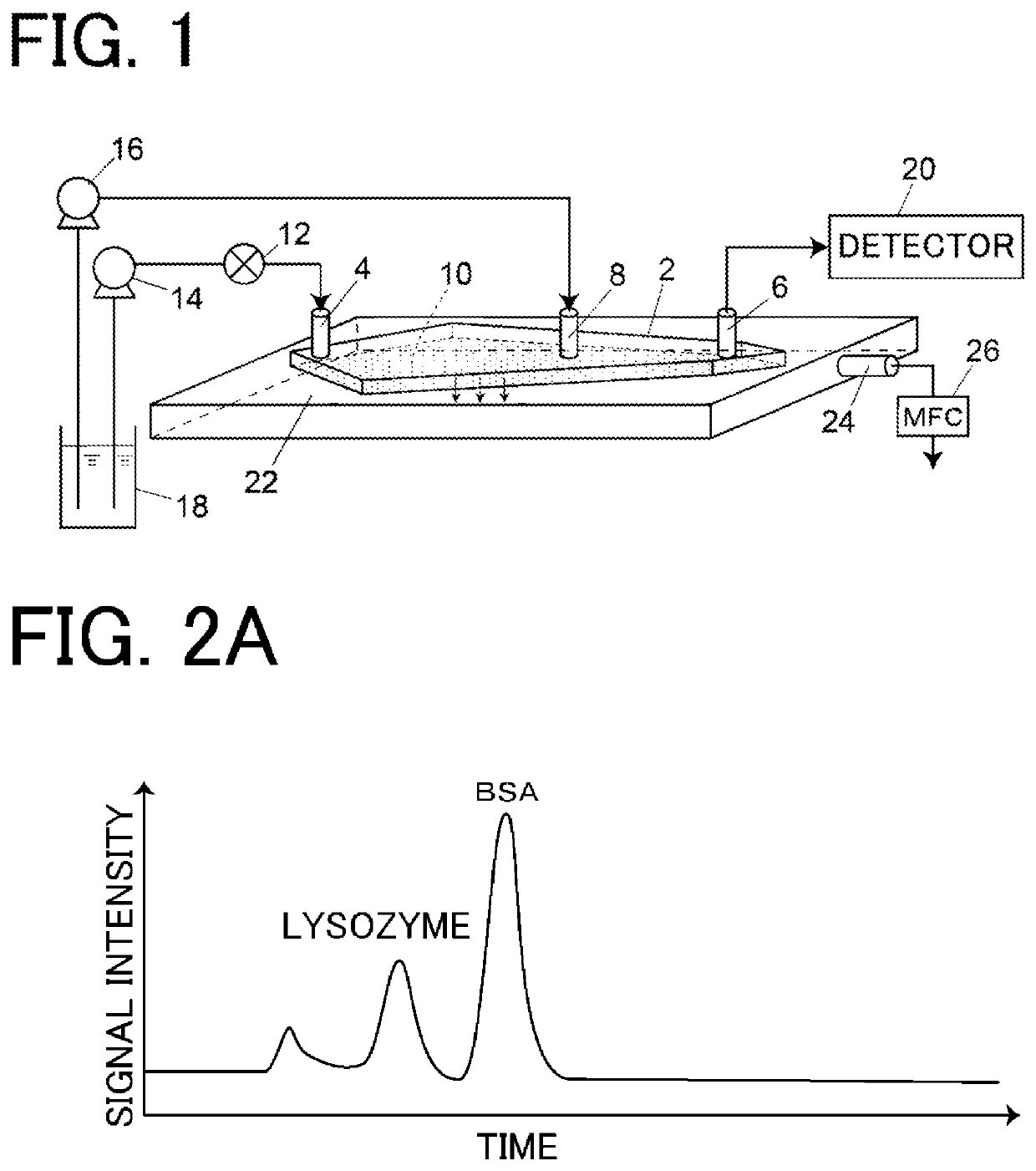
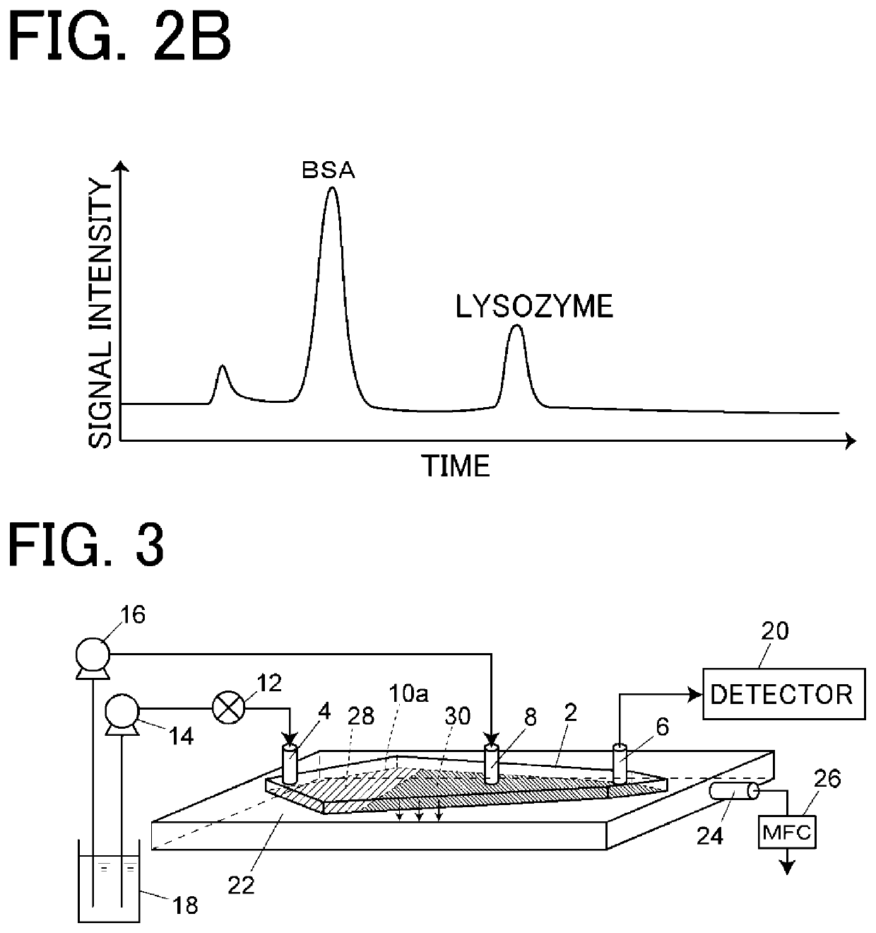
[0016]First, the configuration of the field flow fractionation apparatus of this embodiment will be described with reference to FIG. 1.

[0017]The field flow fractionation apparatus of this embodiment includes a separation channel 2 for separating sample particles. An inlet port 4, an outlet port 6, and an intermediate port 8 communicate with the separation channel 2. The inlet port 4 communicates with one end of the separation channel 2 and the outlet port 6 communicates with the other end of the separation channel 2. The intermediate port 8 is located between the inlet port 4 and the outlet port 6. Although not shown, the separation channel 2 is formed, for example, inside a block formed by stacking a plurality of substrates, and each of the ports 4, 6, and 8 is constituted by a hole provided in the corresponding block.

[0018]The separation channel 2 has a s...


PUM

PropertyMeasurementUnit
particle sizesaaaaaaaaaa
timeaaaaaaaaaa
diffusion coefficientaaaaaaaaaa

Abstract

A field flow fractionation apparatus includes a separation channel provided with an inlet port and an outlet port at both ends and forming a space through which a carrier fluid flows between the inlet port and the outlet port, a separation membrane which is a wall surface that defines the separation channel and is parallel to a channel flow in which a carrier fluid flows in the separation channel from the inlet port toward the outlet port, and has a property of permeating the carrier fluid and not permeating particles to be separated, and a discharge port that discharges the carrier fluid having permeated through the separation membrane to outside. At least a part of the surface of the separation membrane is an ion exchangeable region in which a functional group having ion exchangeability is modified.

Description

BACKGROUND OF THE INVENTION1. Field of the Invention[0001]The present invention relates to a field flow fractionation apparatus for separating and fractionating fine particles contained in a fluid by using field flow fractionation (Field-Flow).2. Description of the Related Art[0002]As a technique for separating and detecting and fractionating fine particles having particle sizes in a wide range of about 1 nm to 50 μm dispersed in a solution, so-called cross-flow field flow fractionation has conventionally been known (see, for example, Japanese Patent Laid-Open No. 2008-000724).[0003]A cross-flow field flow fractionation apparatus adopting an asymmetric channel structure has a separation channel for separating samples. One of the wall surfaces forming the separation channel is a semipermeable membrane having pores, such as regenerated cellulose (RC) and polyethersulfone (PES), and a porous flat plate called frit is provided outside the semipermeable membrane. This wall surface permea...

Claims


Application Information

Patent Timeline
Patent Type & Authority Patents(United States)
IPC IPC(8): G01N30/00
CPCG01N30/0005G01N2030/0025G01N15/00B01D61/00G01N2030/003G01N2030/004B01D2325/42
Inventor OIKAWA, YUKIOHORIIKE, SHIGEYOSHINAKAYA, MAIKOKANAI, MASAKI
Owner SHIMADZU CORP
Why Eureka
Try Eureka