Non-powered drain pump screen device

a screen device and drain pump technology, applied in the direction of filtration separation, separation process, treatment water nature, etc., can solve the problems of inability to remove impurities, damage to the drain pump, and simple screen device for removing impurities may not be able to remove impurities, etc., to improve the efficiency of removal of impurities, improve the efficiency of impurity removal, and facilitate construction and movement

Active Publication Date: 2021-11-16
2H SANEOP INC
View PDF12 Cites 0 Cited by
  • Summary
  • Abstract
  • Description
  • Claims
  • Application Information

AI Technical Summary

Benefits of technology

[0012]Various aspects of the present disclosure provide a non-powered drain pump screen device able to rotate an upper impeller and a lower impeller without power to reduce power consumption and simplify construction and movement, thereby improving the convenience of a user.
[0013]Also provided is a non-powered drain pump screen device able to easily remove impurities using sliding movement of a main stopper.
[0014]Also provided is a non-powered drain pump screen device able to improve durability such that no load is applied to elastic pivot movement of the main stopper.

Problems solved by technology

In such a situation, the flow may be obstructed and may overflow the waterway, thereby damaging areas around the drain pump.
In a worse situation, water may not be able to flow, thereby forming a pool, from which odor may be created.
Accordingly, a simple screen device for removing impurities may not be able to remove impurities.
In addition, when an apparatus for filtering impurities using power is additionally operated, a large amount of costs may be consumed to drive and maintain a motor or a pump.
If the difference in the RPM between the two motors exceeds a range of control set by a user, the sprockets and the chain may be significantly damaged.
Such damage may increase the maintenance costs of the apparatus.

Method used


Image

  • Non-powered drain pump screen device
  • Non-powered drain pump screen device
  • Non-powered drain pump screen device

Examples


Embodiment Construction

[0037]Hereinafter, exemplary embodiments of the present disclosure will be described in detail with reference to the accompanying drawings. It should be understood that the accompanying drawings may not be drawn to scale, and the same elements may be designated by the same reference numerals, even though they may be used in different drawings.

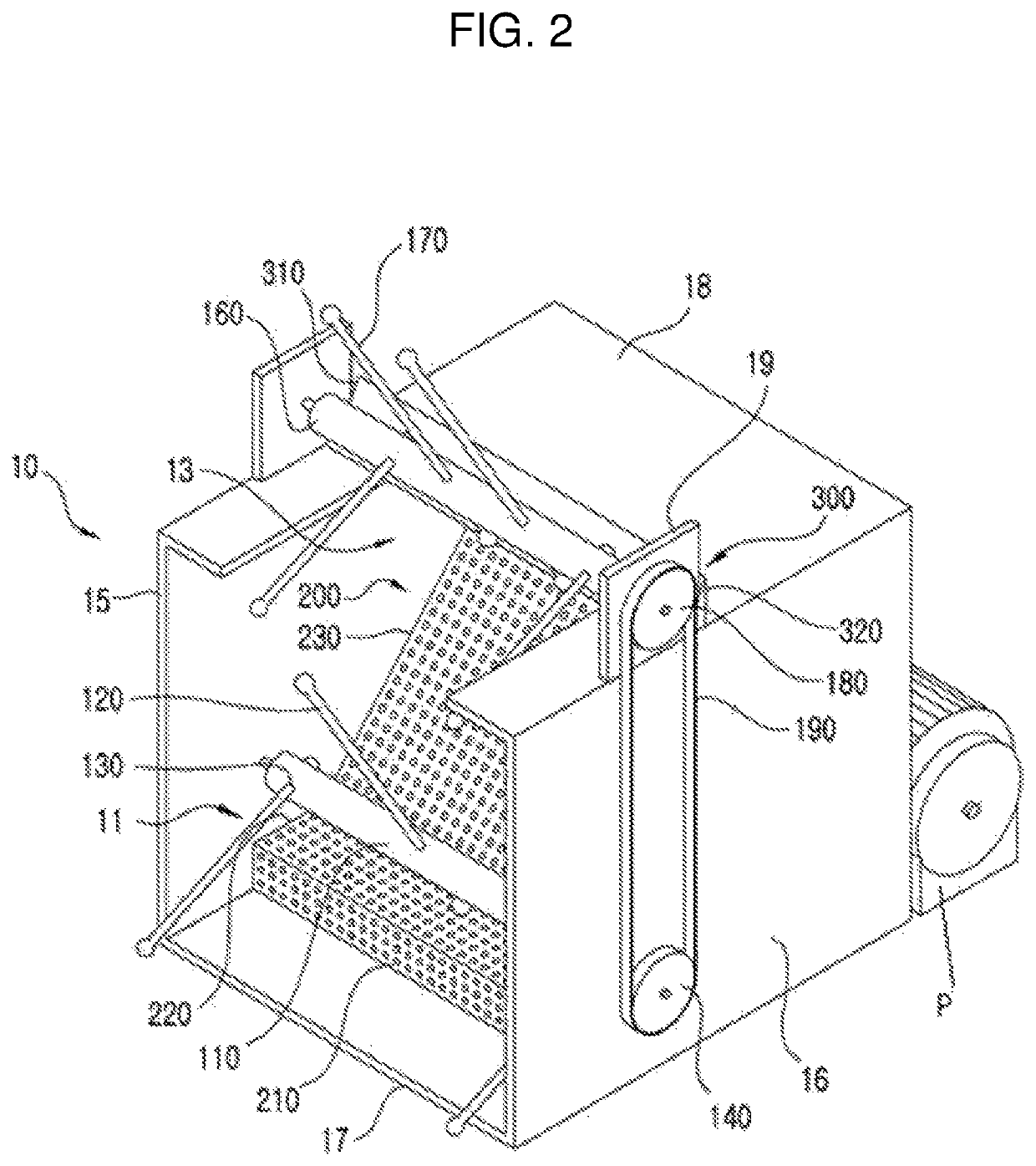
[0038]FIG. 2 is a perspective view illustrating a schematic structure of a screen device according to an embodiment.

[0039]Referring to FIG. 2, it can be appreciated that outer components of the screen device according to the disclosure are generally comprised of a housing 10 and a drain pump P disposed at the rear of the housing 10.

[0040]The housing 10 has a hexahedral shape, and includes an inlet portion 11 defined by an open front portion to intake fluid, a rear portion 12 (see FIG. 4) located opposite the inlet portion 11, and an outlet portion 1 (see FIG. 4) to discharge fluid. In addition, the housing 10 may include: an upper open area 13 ...


PUM

PropertyMeasurementUnit
lengthaaaaaaaaaa
gravityaaaaaaaaaa
heightaaaaaaaaaa

Abstract

A non-powered drain pump screen device is disposed in a river, a stream, a waterway, or a place in which a significant amount soil is carried by a water flow. Upper and lower impellers are provided with upper and lower blades. The lower blades prevent reentry of impurities while rotating due to resistance to a flow of fluid in a non-powered manner. The upper impellers are rotated in a non-powered manner, so that the upper blades filter impurities. The non-powered drain pump screen device is disposed in a waterway to remove impurities at low maintenance costs.

Description

CROSS REFERENCE TO RELATED APPLICATION[0001]The present application claims priority to Korean Patent Application No. 10-2018-0134524 filed in the Republic of Korea on Nov. 5, 2018, Korean Patent Application No. 10-2019-0124625, filed in the Republic of Korea on Oct. 8, 2019, Korean Patent Application No. 10-2019-0124629, filed in the Republic of Korea on Oct. 8, 2019, which are hereby incorporated by reference for all purposes as if fully set forth herein.BACKGROUNDField[0002]The present disclosure relates to a drain pump screen device and, more particularly, to a system for removing impurities from fluid entering a drain pump using a non-powered screen device.Description[0003]In general, an impurity removing device for a drain pump is disposed in a specific location in a river or a stream into which sewage and supply water flows, an overflowing waterway, or the like. Soil, impurities, or various types of living waste carried by a water flow may reach the drain pump, unless removed ...

Claims


Application Information

Patent Timeline
Patent Type & Authority Patents(United States)
IPC IPC(8): B01D29/64E03F5/14B01D33/80B01D33/52B01D29/72B01D29/03B01D29/52B01D29/96B01D29/60C02F1/00B01D29/94C02F103/00
CPCB01D29/6476B01D29/03B01D29/52B01D29/60B01D29/72B01D29/94B01D29/965B01D33/52B01D33/802C02F1/004E03F5/14C02F2103/001C02F2303/16C02F2303/24
Inventor KANG, BYEONGGWON
Owner 2H SANEOP INC
Why Eureka
Try Eureka