
Chassis link for a motor vehicle

a technology for chassis links and motor vehicles, applied in mechanical devices, transportation and packaging, other domestic objects, etc., can solve problems such as compressive loading and reduced stiffness, and achieve the effects of/or buckling strength, increasing adhesion surface, and increasing bending stiffness and/or torsional stiffness

Active Publication Date: 2021-11-16
ZF FRIEDRICHSHAFEN AG
View PDF15 Cites 4 Cited by
  • Summary
  • Abstract
  • Description
  • Claims
  • Application Information

AI Technical Summary

Benefits of technology

[0006]Accordingly, one aspect of the invention provides a component part for a motor vehicle. The component part has a hollow profile portion made from a fiber-reinforced plastic and a load introduction element made from a metal material. The hollow profile portion and the load introduction element are connected to one another in a common connection portion via a nondetachable, glued plug-in connection. In the plug-in connection, an end portion of the load introduction element and an end portion of the hollow profile portion mutually engage in one another at least substantially by positive engagement. According to one aspect of the invention, the component part is formed as a chassis link for a motor vehicle, and the end portion of the load introduction element has a spline with teeth extending at least substantially in longitudinal direction of the common connection portion so that the stiffness of the end portion of the load introduction element is reduced in longitudinal direction of the common connection portion.
[0035]Preferably, at least one intermediate space between two teeth is filled exclusively with an adhesive inside of the connection portion. In particular, this adhesive at the same time forms a part of the outer circumferential surface of the connection portion. In particular, the adhesive is located between the at least two teeth in a through-slot with constant width. Particularly when such a through-slot with constant width is milled or sawed, it is contemplated to produce the through-slot in a continuous manner perpendicular to the longitudinal direction of the connection portion in order to prevent increased machining costs, for example, by plunge milling. If an intermediate space, which is not filled by the end portion of the hollow profile portion, for example, a rib of this end portion, should result between two teeth when the through-slot is produced in a continuous manner, it is recommended that this intermediate space be filled with the adhesive in order to protect the intermediate space from soiling and possibly also against corrosion through dirt, dust, splashing water or road salt, etc. during driving operation. In particular, the intermediate space is filled in such a way that the adhesive is flush with the outer circumference of the connection portion.

Problems solved by technology

In particular, this reduced stiffness results during compressive loading when the hollow profile portion is not inserted into the spline up to the stop in longitudinal direction of the common connection portion but rather a gap remains between a front side of the hollow profile portion facing the load introduction element and a base of the spline.

Method used


Image

  • Chassis link for a motor vehicle
  • Chassis link for a motor vehicle
  • Chassis link for a motor vehicle

Examples


Embodiment Construction

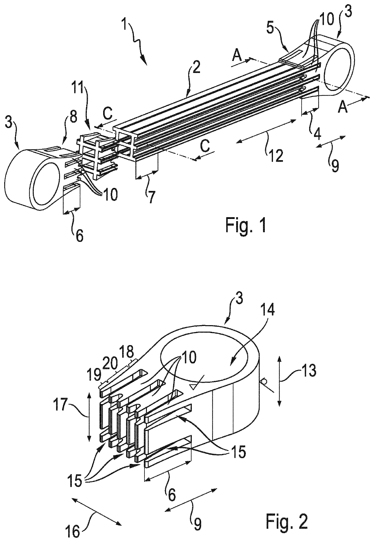
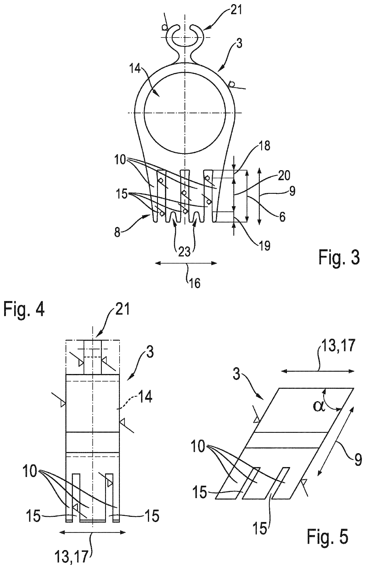
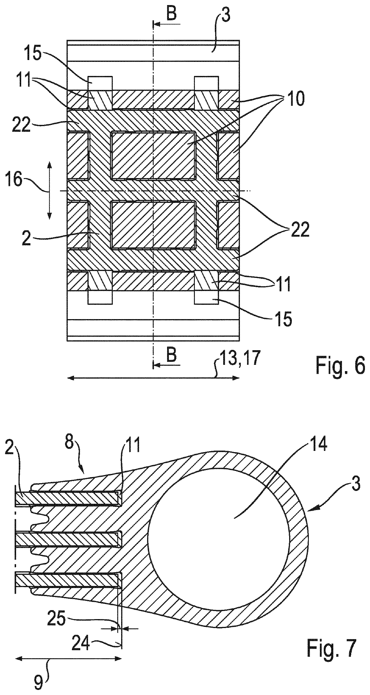
[0049]FIG. 1 shows a chassis link 1, also referred to as axle strut, formed as a two-point link. The chassis link 1 has a pultruded hollow profile portion 2 of fiber-reinforced plastic and two load introduction elements 3 of aluminum. The hollow profile portion 2 and the load introduction elements 3 are connected to one another in common connection portions 4 via nondetachable glued plug-in connections 5. With respect to the two plug-in connections 5, an end portion 6 of the load introduction element 3 and an end portion 7 of the hollow profile portion 2 mutually engage one inside the other substantially in positive engagement. The end portion 6 of the load introduction element 3 has a spline 8 with twelve teeth 10 extending in longitudinal direction 9 of the common connection portion 4 so that the stiffness of the end portion 6 of the load introduction element 3 in longitudinal direction 9 of the common connection portion 4 is reduced. In the common connection portion 4, the end po...


PUM

PropertyMeasurementUnit
angleaaaaaaaaaa
angleaaaaaaaaaa
angleaaaaaaaaaa

Abstract

A component part for a motor vehicle having a hollow profile portion of a fiber-reinforced plastic and a load introduction element of a metal material. The hollow profile portion and the load introduction element are connected in a common connection portion via a nondetachable, glued plug-in connection in which an end portion of the load introduction element and an end portion of the hollow profile portion engage in one another by positive engagement. The end portion of the load introduction element has a spline with teeth extending in longitudinal direction of the common connection portion so that the stiffness of the end portion of the load introduction element reduced in longitudinal direction of the common connection portion.

Description

CROSS REFERENCE TO RELATED APPLICATIONS[0001]This is a U.S. national stage of Application No. PCT / EP2019 / 060844 filed Apr. 29, 2019. Priority is claimed on German Application No. DE 10 2018 208 282.0 filed May 25, 2018 the content of which is incorporated herein by reference.BACKGROUND OF THE INVENTION1. Field of the Invention[0002]The invention is directed to a component part for a motor vehicle, having a hollow profile portion made of a fiber-reinforced plastic and a load introduction element made of a metal material.2. Description of Related Art[0003]Component parts for motor vehicles having a hollow profile portion made of a fiber-reinforced plastic and a load introduction element made of a metal material are known from the prior art. A strut-shaped component part of fiber-reinforced plastic which is formed as a tubular hollow profile is disclosed in DE 10 2010 053 843 A1. The strut-shaped component part is connected via a nondetachable plug-in connection to a load introduction ...

Claims


Application Information

Patent Timeline
Patent Type & Authority Patents(United States)
IPC IPC(8): B60G7/00B29C70/52B29K31/00B29L31/00B29L31/30
CPCB60G7/001B29C70/52B29K2031/00B29L2031/003B29L2031/3002B60G2206/012B60G2206/11B60G2206/7101F16C7/026F16C2226/40B29C66/52431B29C66/5244B29C66/52451B29C66/534B29C66/721B29C66/742B29C65/48B29C66/12441B29C65/5085B29C66/524B29C66/5243B29C66/1248B29L2031/75
Inventor STIEGLITZ, ANDRESCHWARZ, THOMASMÜLLER, INGOLF
Owner ZF FRIEDRICHSHAFEN AG
Learn More