Speed reduction device and brake actuator including ihe same

a technology of brake actuator and speed reduction device, which is applied in the direction of brake system, mechanical equipment, gearing, etc., can solve the problems of obviating a cost increase and undesirable pushing up the cost of the device, and achieves compact size and good load balan

Active Publication Date: 2021-11-16
TOYOTA JIDOSHA KK
View PDF11 Cites 0 Cited by
  • Summary
  • Abstract
  • Description
  • Claims
  • Application Information

AI Technical Summary

Benefits of technology

[0004]Though the speed reduction device disclosed in Japanese Patent Application Publication No. 5-321990 is considerably compact in size, it includes bearings used exclusively for the device, undesirably pushing up the cost of the device. Thus, there is much room for improvement in the speed reduction device, and some modifications enable achievement of a speed reduction device having high utility. Accordingly, one aspect of the present disclosure is directed to a speed reduction device having high utility. Another aspect of the present disclosure is directed to a brake actuator having high utility owing to employment of the speed reduction device.

Problems solved by technology

Though the speed reduction device disclosed in Japanese Patent Application Publication No. 5-321990 is considerably compact in size, it includes bearings used exclusively for the device, undesirably pushing up the cost of the device.
Further, the present speed reduction device has fewer restrictions on bearings, and general-purpose bearings are available in the present speed reduction device, thus obviating a cost increase.

Method used


Image

  • Speed reduction device and brake actuator including ihe same
  • Speed reduction device and brake actuator including ihe same
  • Speed reduction device and brake actuator including ihe same

Examples


Embodiment Construction

[0030]Referring to the drawings, there will be explained below in detail a speed reduction device according to one embodiment of the present disclosure and a brake actuator according to one embodiment of the present disclosure including the speed reduction device. It is to be understood that the present disclosure is not limited to the details of the following embodiment but may be embodied with other changes and modifications based on the knowledge of those skilled in the art.

A. Electric Brake Device Including Brake Actuator

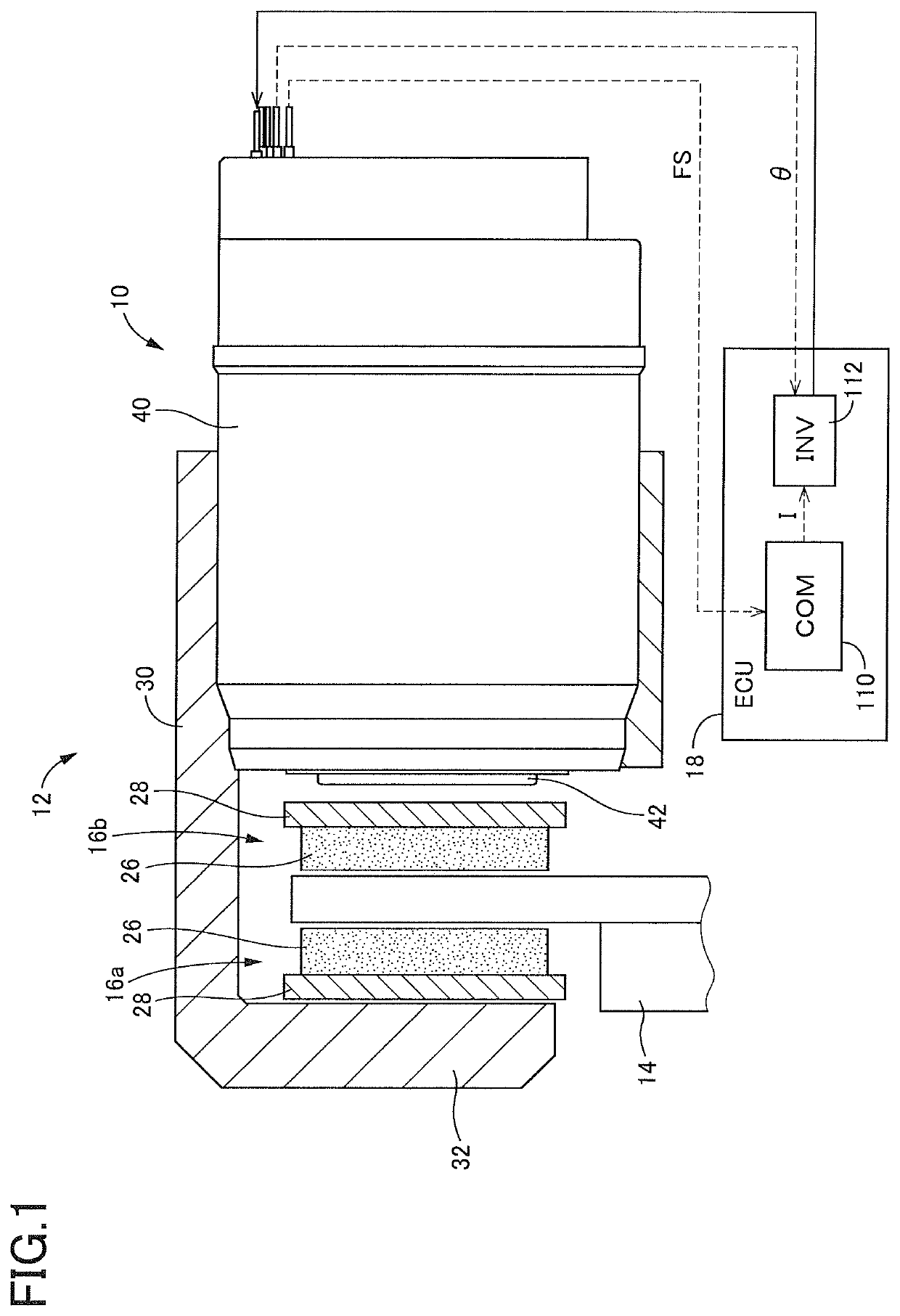
[0031]As shown in FIG. 1, a brake actuator 10 (hereinafter simply referred to as “actuator 10” where appropriate) according to the present embodiment is employed in an electric brake device as a major constituent element. The electric brake device includes: a brake caliper 12 (hereinafter simply referred to as “caliper 12” where appropriate) that holds the actuator 10; a disc rotor 14, as a rotary body, configured to rotate with a wheel; a pair of brake pads 16a...


PUM


Abstract

A speed reduction device including a first internally meshing planetary gear mechanism and a second internally meshing planetary gear mechanism, including: a housing; an input shaft rotatably supported by the housing at its first shaft portion through a first bearing; a planetary gear member rotatably supported by an eccentric shaft portion of the input shaft through a second bearing; and an output shaft rotatably supported by a second shaft portion of the input shaft through a third bearing, wherein a distance in an axial direction between a first support position and a second support position is equal to a distance in the axial direction between the second support position and a third support position, and a distance in the axial direction between the second support position and an input-side meshing position is equal to a distance in the axial direction between the second support position and an output-side meshing position.

Description

CROSS REFERENCE TO RELATED APPLICATION[0001]The present application claims priority from Japanese Patent Application No. 2018-218541, which was filed on Nov. 21, 2018, the disclosure of which is herein incorporated by reference in its entirety.BACKGROUNDTechnical Field[0002]The following disclosure relates to a speed reduction device including an internally meshing planetary gear mechanism and also relates to a brake actuator including the speed reduction device and configured to stop rotation of a wheel.Description of Related Art[0003]In recent years, a brake actuator as disclosed in Japanese Patent Application Publication No. 2014-109315, for instance, has been actively developed. The brake actuator includes an electric motor as a drive source and is configured to give, to a wheel, a braking force whose magnitude corresponds to a force generated by the electric motor. For achieving the brake actuator that is compact in size, it is desirable to employ a speed reduction device whose...

Claims


Application Information

Patent Timeline
Patent Type & Authority Patents(United States)
IPC IPC(8): F16H1/32F16H1/34F16D65/18
CPCF16H1/321F16D65/18F16H1/34F16H1/32F16D2121/24B60T13/746F16H2001/327F16H25/20F16D2066/005F16D2125/50F16D2125/40F16D2055/0029F16D2066/003
Inventor NISHIGAYA, SHINYAYAMAUCHI, YOJI
Owner TOYOTA JIDOSHA KK
Why Eureka
Try Eureka