Suspension system for vehicle

Inactive Publication Date: 2010-08-19
TOYOTA JIDOSHA KK
View PDF5 Cites 21 Cited by
  • Summary
  • Abstract
  • Description
  • Claims
  • Application Information

AI Technical Summary

Benefits of technology

[0006]The vehicle suspension system described in each of the above-indicated Patent Documents is capable of restraining or suppressing roll of a vehicle body by applying a stabilizer force generated by the stabilizer apparatus as a roll restraining force. In the systems described in the above-indicated Patent Documents 1 and 2, the roll of the vehicle is restrained by controlling only the stabilizer force. The system described in the above-indicated Patent Document 3 includes, in addition to the stabilizer apparatus, a hydraulic shock absorber (hereinafter abbreviated as “absorber” where appropriate) configured to change a damping coefficient, and the roll of the

Problems solved by technology

Accordingly, there may be a risk of deterioration in a roll restraining effect in an instance where the damping coefficient that is a b

Method used


Image

  • Suspension system for vehicle
  • Suspension system for vehicle
  • Suspension system for vehicle

Examples


Embodiment Construction

[0046]There will be described in detail one embodiment according to the claimable invention, referring to the drawings. It is to be understood, however, that the claimable invention is not limited to the details of the following embodiment but may be embodied with various changes and modifications, such as those described in the FORMS OF THE CLAIMABLE INVENTION, which may occur to those skilled in the art.

1. Structure of Suspension System

1.1. Overall Structure of Suspension System

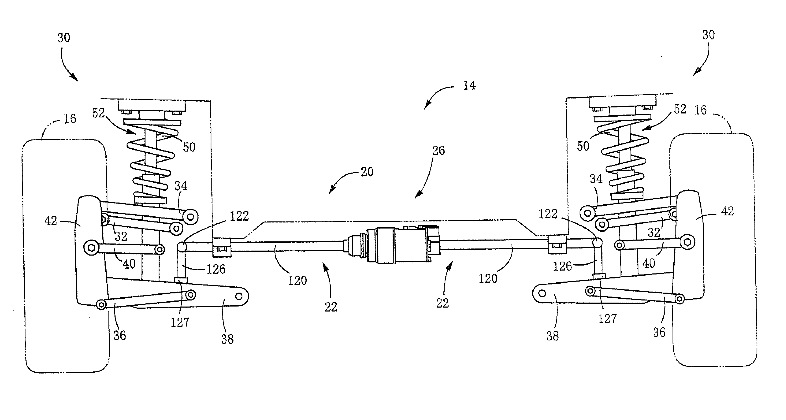
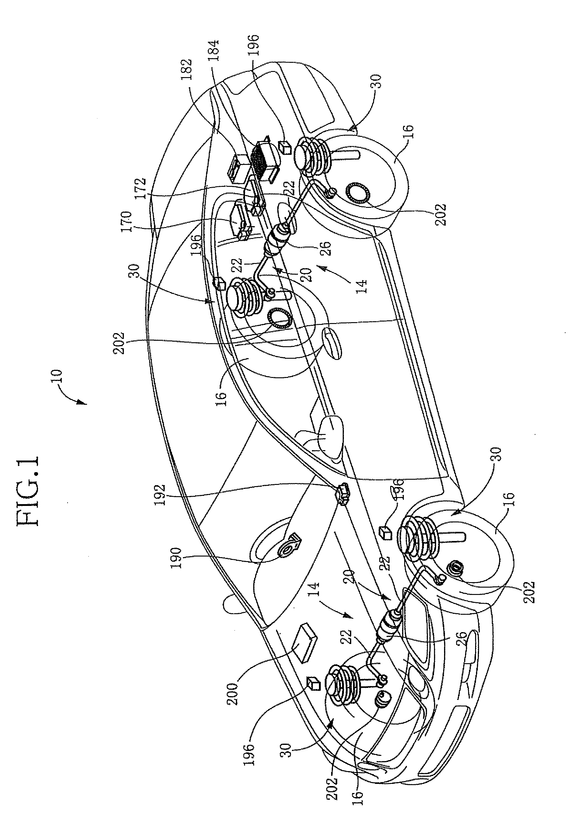
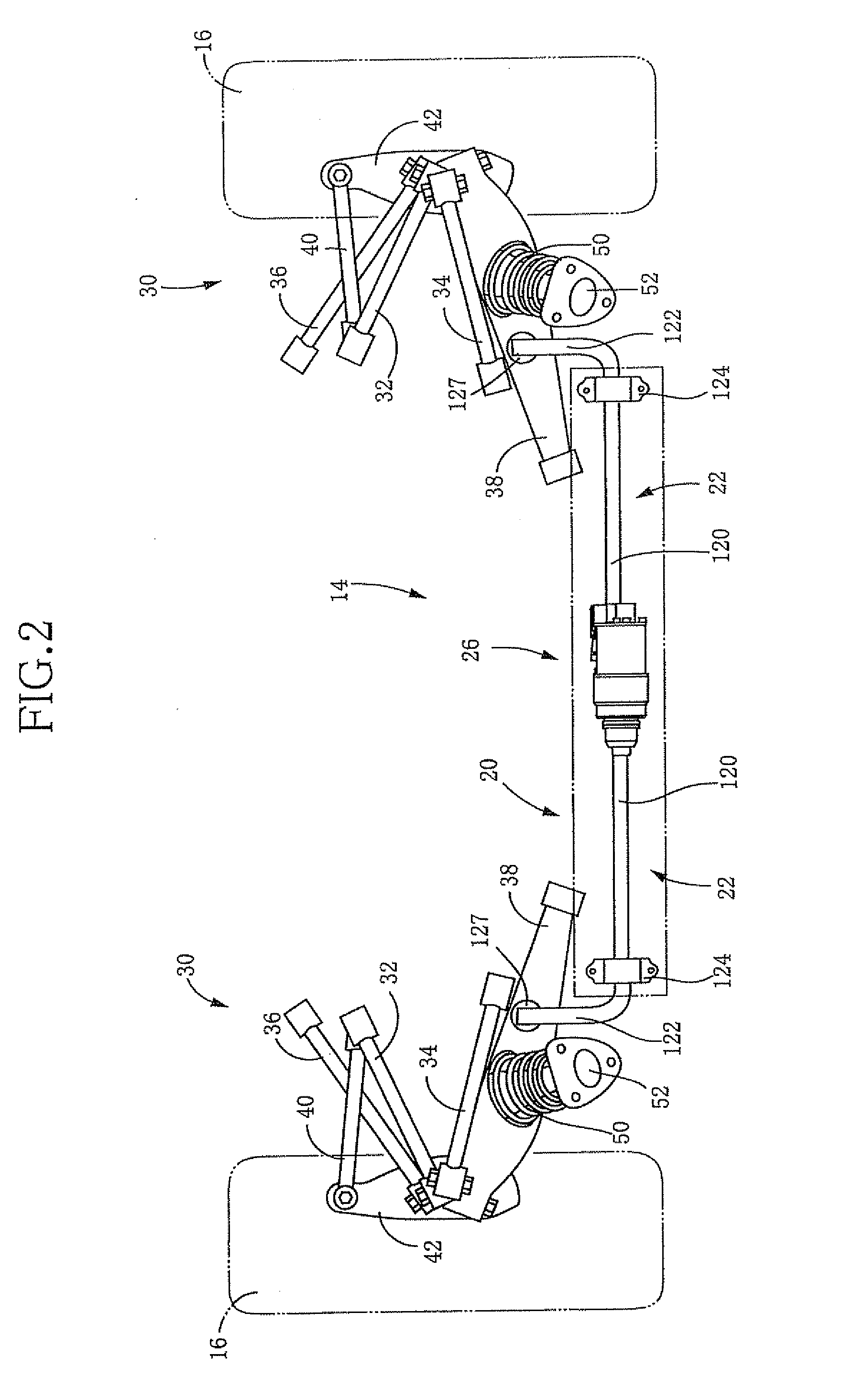
[0047]FIG. 1 schematically shows a suspension system 10 for a vehicle according to the present embodiment. The suspension system 10 includes a pair of stabilizer apparatuses 14, 14 which are respectively disposed on a front-wheel side and a rear-wheel side, of the vehicle. Each stabilizer apparatus 14 includes a stabilizer bar 20 whose opposite ends are respectively connected to wheel-holding members in the form of suspension arms (FIGS. 2 and 3) for holding left and right wheels 16, respectively. The stabi...


PUM


Abstract

A suspension system for a vehicle, including: a stabilizer apparatus configured to change a stabilizer force by an operation of an actuator; a pair of absorbers of a hydraulic type each configured to change a damping coefficient thereof: a control device which includes (a) a stabilizer-force control portion configured to control the stabilizer force in accordance with roll moment acting on a body of the vehicle and (b) a damping-coefficient control portion configured to control the damping coefficient of each of the absorbers, wherein the damping-coefficient control portion is configured to execute a damping-coefficient reduction control for reducing the damping coefficient of each of the absorbers when a prescribed condition is satisfied and wherein the stabilizer-force control portion is configured to increase the stabilizer force in an instance where the damping-coefficient reduction control is under execution, as compared with an instance where the damping-coefficient reduction control is not under execution.

Description

TECHNICAL FIELD[0001]The present invention relates in general to a suspension system for a vehicle including a stabilizer apparatus configured such that a stabilizer force generated by the stabilizer apparatus is changeable by an operation of an actuator.BACKGROUND ART[0002]In recent years, there has been developed and actually used a stabilizer system for a vehicle described in the following patent documents, namely, a stabilizer system including a stabilizer apparatus configured to controllably generate a stabilizer force that is based on a twist-reacting force of a stabilizer bar. Here, the twist-reacting force means a force exerted by the stabilizer bar as a result of being twisted.[0003]Patent Document 1 JP-A-2005-238972[0004]Patent Document 2 JP-A-2006-256539[0005]Patent Document 3 JP-A-2007-83853DISCLOSURE OF THE INVENTION(A) Summary of the Invention[0006]The vehicle suspension system described in each of the above-indicated Patent Documents is capable of restraining or suppr...

Claims


Application Information

Patent Timeline
IPC IPC(8): B60G21/055
CPCB60G17/0162B60G2800/9122B60G17/08B60G21/0555B60G2200/18B60G2202/42B60G2204/1242B60G2204/128B60G2204/4191B60G2400/102B60G2400/104B60G2400/204B60G2400/41B60G2400/821B60G2400/91B60G2500/102B60G2500/11B60G2600/02B60G2600/182B60G2600/184B60G2800/012B60G2800/162B60G17/0165
Inventor SANO, KATSUYUKI
Owner TOYOTA JIDOSHA KK
Why Eureka
Try Eureka