Apparatus and method for producing an enriched medical suspension
- Summary
- Abstract
- Description
- Claims
- Application Information
AI Technical Summary
Benefits of technology
Problems solved by technology
Method used
Image
Examples
first embodiment
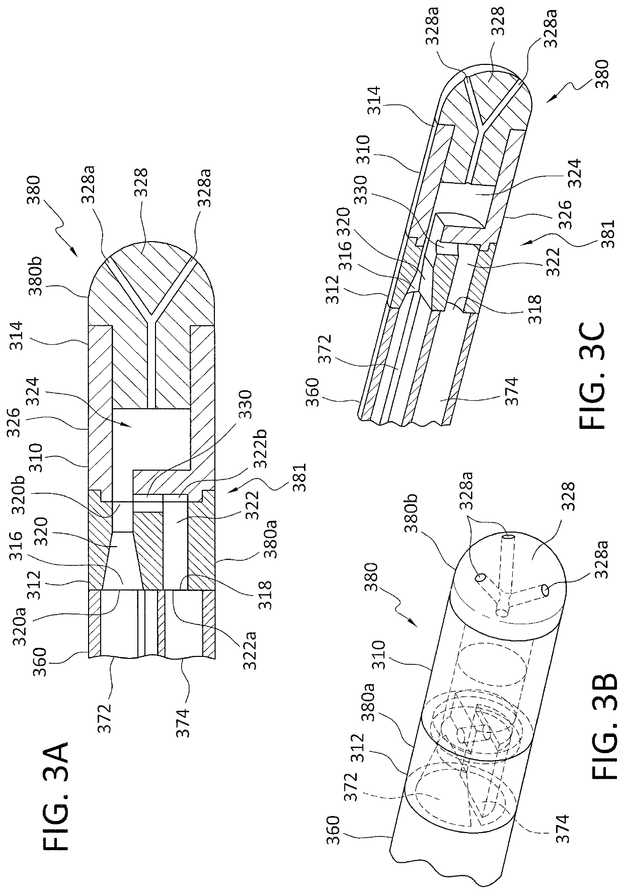
[0028]It is appreciated various tip assemblies and enriched medical suspension generating structures may be employed in accordance with the present invention. In accordance with a first embodiment as shown with reference to FIGS. 3A-3C, the Venturi-agitating tip assembly 380 employs a Venturi arrangement with a mixing chamber 324. The Venturi-agitating tip assembly 380 has a proximal first end 380a and a distal second end 380b. The Venturi-agitating tip assembly 380 includes a hollow cylindrical elongated body 310 having a proximal first end 312, which coincides with the proximal first end 380a of the Venturi-agitating tip assembly 380, and a distal second end 314. The proximal first end 380a of the Venturi-agitating tip assembly 380 includes a multi-channel arrangement 381 including first and second inputs 316, 318 for attachment to the dual lumen catheter 360. The first and second inputs 316, 318 respectively lead to a first channel 320 and a second channel 322 of the multi-channe...
second embodiment
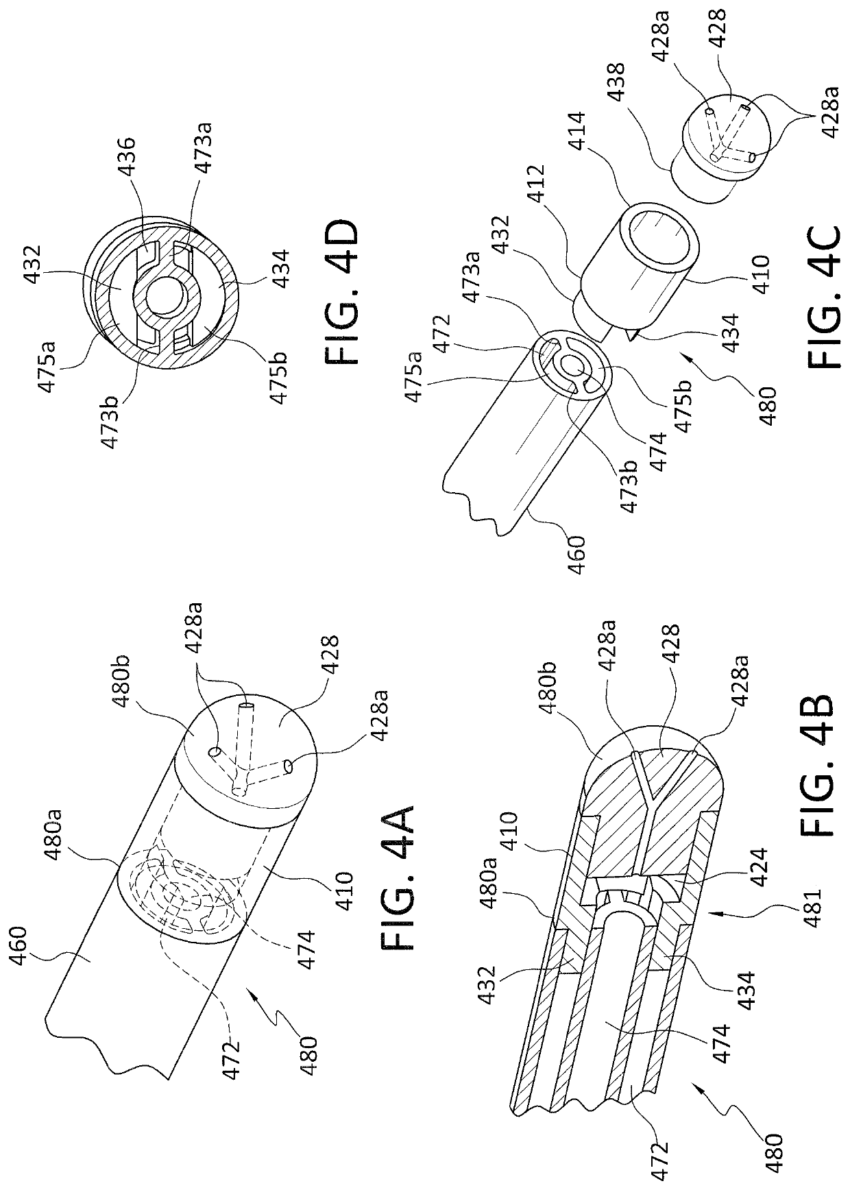
[0033]In accordance with a second embodiment as shown with reference to FIGS. 4A-4D, a Venturi-agitating tip assembly 480 employs a spray tip 428 in conjunction with a multi-channel arrangement 481 where the pressurized chemical solution and medical solution are mixed and forced through the spray tip 428. The Venturi-agitating tip assembly 480 includes a proximal first end 480a and a distal second end 480b. The Venturi-agitating tip assembly 480 includes a hollow cylindrical elongated body 410 having a proximal first end 412, which coincides with the proximal first end 480a of the Venturi-agitating tip assembly 480, and a distal second end 414. The Venturi-agitating tip assembly 480 is adapted for use with a dual lumen catheter 460, in particular a dual lumen catheter having concentric lumens, wherein the outer first lumen 472 is annular shaped for the passage of pressurized chemical solution (and has an outer diameter of 0.092 inches at the outer wall thereof and an inner diameter ...
third embodiment
[0038]In accordance with a third embodiment as shown with reference to FIGS. 5A-5E, a Venturi-agitating tip assembly 780 employs a tip 728 in conjunction with a multi-channel arrangement 781 where the pressurized chemical solution and medical solution are mixed to form an enriched medical suspension and forced through the tip 728. The Venturi-agitating tip assembly 780 includes proximal first end 780a and a distal second end 780b. The Venturi-agitating tip assembly 780 includes a hollow cylindrical elongated body 710 having a proximal first end 712, which coincides with the proximal first end 780a of the Venturi-agitating tip assembly 780, and a distal second end 714. The Venturi-agitating tip assembly 780 is adapted for use with a multi-lumen catheter 760, in particular a triple lumen catheter having parallel lumens, wherein the first and second lumens 772, 773 are circular shaped (each with a diameter of 0.039 inches) and are dimensioned for the passage of pressurized chemical sol...
PUM
 Abstract
Description
Claims
Application Information
 - R&D
- Intellectual Property
- Life Sciences
- Materials
- Tech Scout
- Unparalleled Data Quality
- Higher Quality Content
- 60% Fewer Hallucinations
Browse by: Latest US Patents, China's latest patents, Technical Efficacy Thesaurus, Application Domain, Technology Topic, Popular Technical Reports.
© 2025 PatSnap. All rights reserved.Legal|Privacy policy|Modern Slavery Act Transparency Statement|Sitemap|About US| Contact US: help@patsnap.com


