
Quick detaching mechanism for handle light

a technology of detachable mechanism and handle, which is applied in the field of tactical lights, can solve the problems of inconvenient operation and use, and achieve the effects of convenient use, quick detachable mechanism, and quick mounting and detachmen

Active Publication Date: 2021-12-07
OLIGHT GRP CO LTD
View PDF6 Cites 2 Cited by
  • Summary
  • Abstract
  • Description
  • Claims
  • Application Information

AI Technical Summary

Benefits of technology

Enables quick and convenient mounting and detachment of the handle light on a firearm rail, with enhanced clamping force and stability, reducing the number of accessories needed and simplifying operation.

Problems solved by technology

The handle light in the prior art combines the handle and the tactical light, but when using the handle light, one often needs tools to detach or mount the handle light, resulting in inconvenient operation and use.

Method used


Image

  • Quick detaching mechanism for handle light
  • Quick detaching mechanism for handle light
  • Quick detaching mechanism for handle light

Examples


embodiment 1

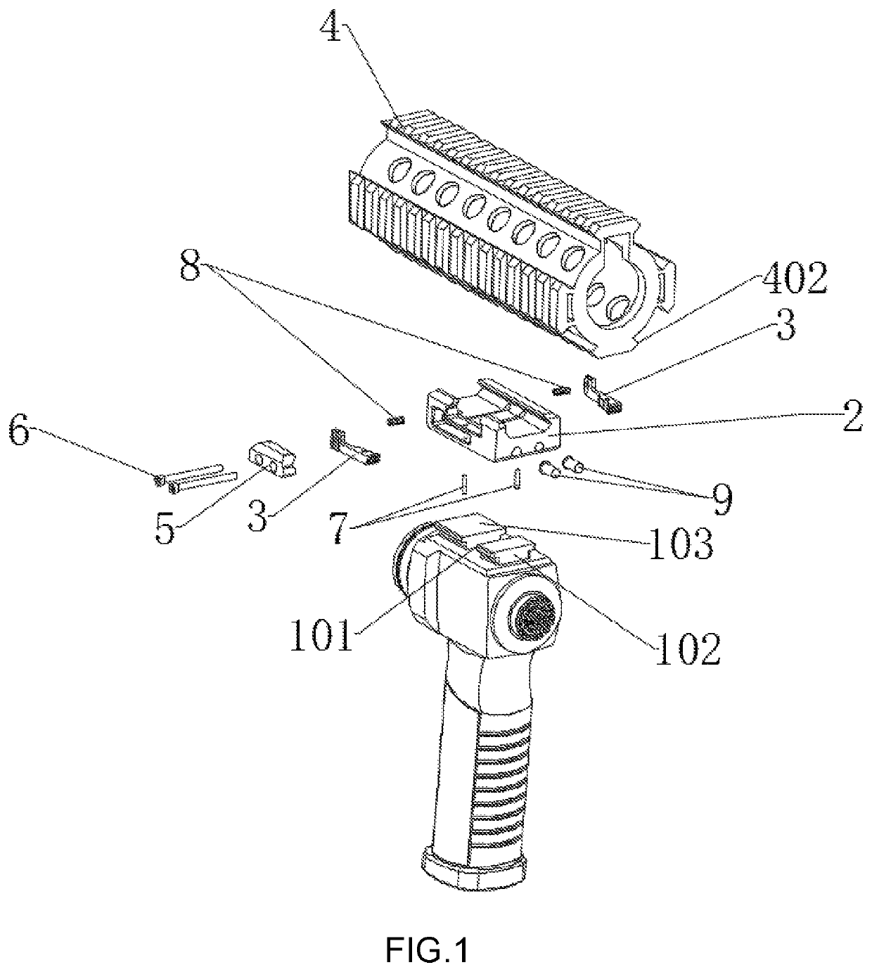
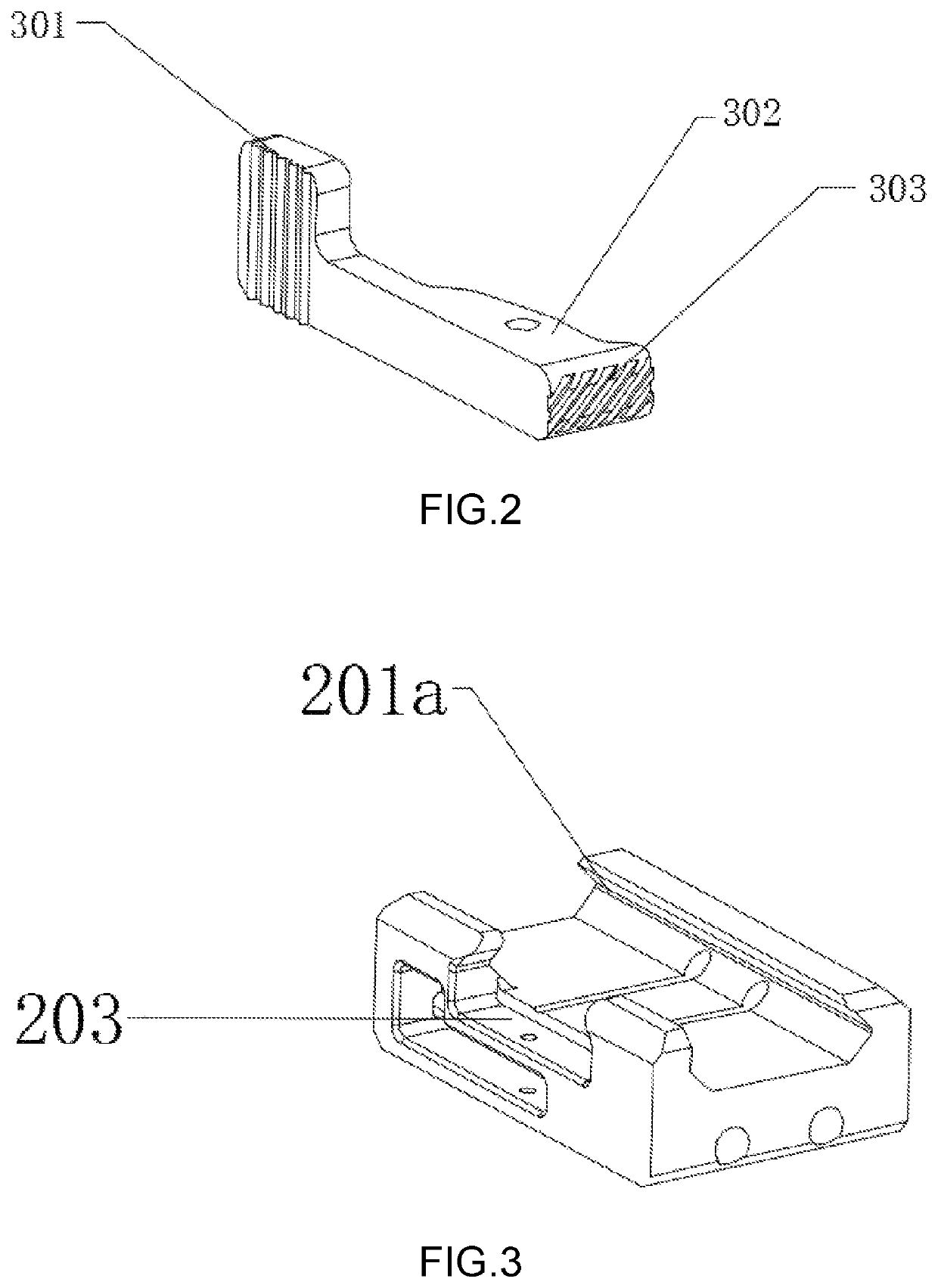
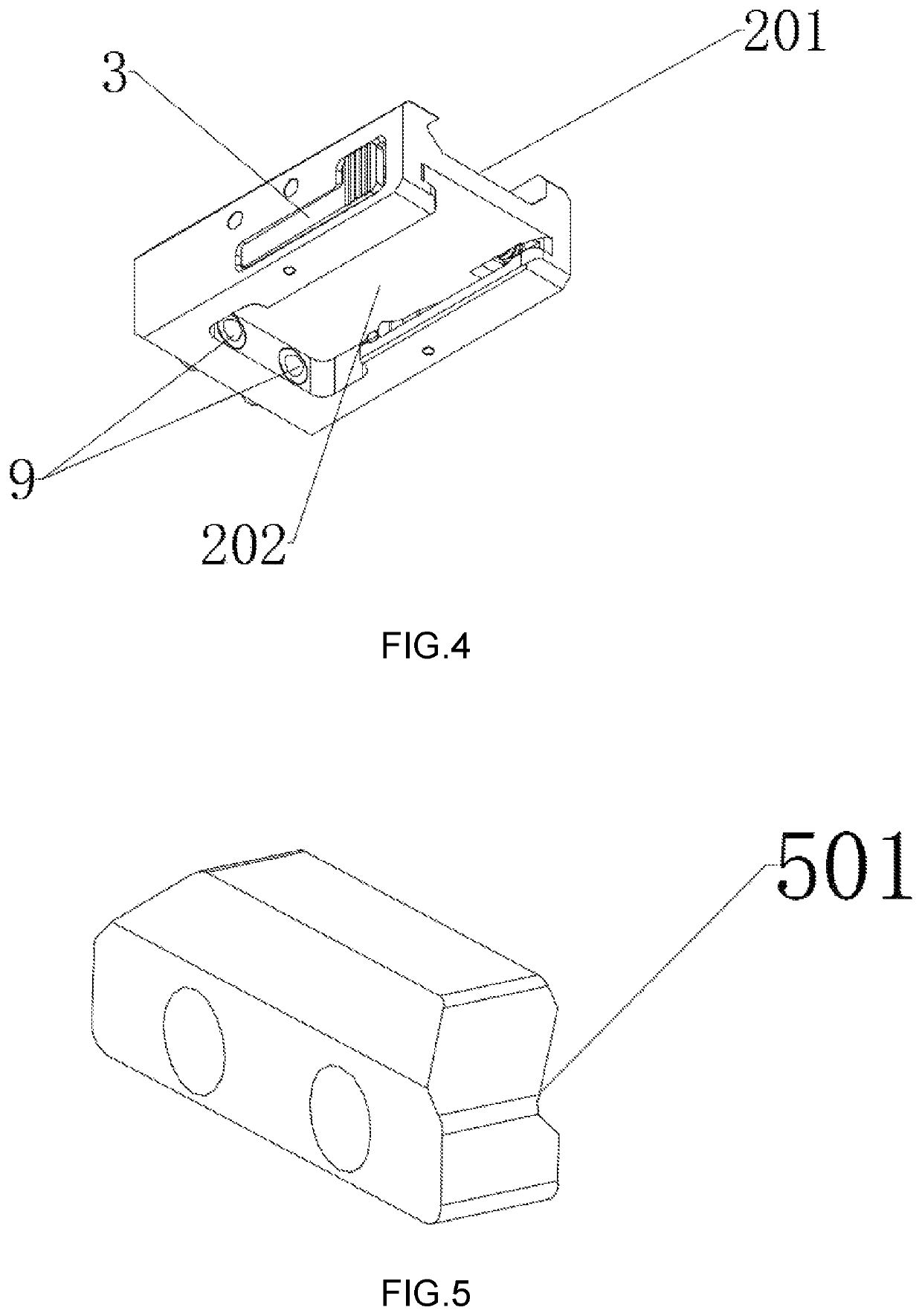
[0053] A quick detaching mechanism for handle light comprises a handle light 1, a base 2 and a locking rod 3. The base 2 has a top which is provided with a mounting slot 201. The firearm rail 4 slides along the mounting slot 201 to insert into the top of the base 2, and is fixed by cooperation of a movable lock block 5 and a screw 6. The locking rod 3 is located on one side of the base 2 and is connected to the base 2 via a rotating shaft 7. The locking rod 3 comprises a snapping member 302 and a pressing member 301. The snapping member 302 and the pressing member 301 are respectively disposed on two sides of the rotating shaft 7. The top of the handle light 1 is provided with a first T-shaped block 102 and a second T-shaped block 103. A handle light slot 101 is located between the first T-shaped block 102 and the second T-shaped block 103. The bottom of the base 2 is provided with a sliding slot 202. The first T-shaped block 102 and the second T-shaped block 103 are inserted into t...

embodiment 2

[0054] A quick detaching mechanism for handle light comprises a handle light 1, a base 2 and two locking rods 3. The base 2 has a top which is provided with a mounting slot 201. The firearm rail 4 slides along the mounting slot 201 to insert into the top of the base 2. The top of the base 2 is mounted on the firearm rail 4 via a screw 6. The screw 6 is used to limit the degree of freedom of the base 2 in the front-rear direction. The locking rods 3 are respectively located on two sides of the base 2. Each of the locking rods 3 is provided with a snapping member 302 and a pressing member 301. The snapping member 302 and the pressing member 301 are respectively disposed on two sides of the rotating shaft 7. The top of the handle light 1 is provided with a first T-shaped block 102 and a second T-shaped block 103. A handle light slot 101 is located between the first T-shaped block 102 and the second T-shaped block 103. Each of the snapping members 302 has a slope structure. The bottom o...


PUM


Abstract

This invention provides a quick detaching mechanism for handle light, including a handle light, a base and a locking rod; the base is rotatably connected to the locking rod; the locking rod detachably mounts the handle light on a bottom of the base; the base has a top which is mounted on a firearm rail. Through the cooperation of the base and the locking rod, the handle light with the handle and the tactical light combined can be quickly mounted on and detached from the firearm rail. The mounting and detachment processes can be completed by only controlling the locking rod. It is convenient to use and no other tools is required. Its operation is simple and convenient.

Description

BACKGROUND OF THE INVENTION[0001]The present invention relates to the technical field of tactical lights, and more specifically relates to a quick detaching mechanism for handle light.[0002]In the market of tactical lights for long firearms, many firearms require additional firearm rails to mount firearm accessories. Firearm accessories are often mounted below or on the side of the firearm rail. Generally, a handle is also required to be mounted for easy holding and maintaining shooting stability. It is also necessary to mount a tactical light as a firearm accessory for auxiliary lighting.[0003]Common firearm handles and tactical lights are two separate firearm accessories. The handle and the tactical light need to be detached and mounted separately. The handle light in the prior art combines the handle and the tactical light, but when using the handle light, one often needs tools to detach or mount the handle light, resulting in inconvenient operation and use.BRIEF SUMMARY OF THE I...

Claims


Application Information

Patent Timeline
Patent Type & Authority Patents(United States)
IPC IPC(8): F41C23/16F41G11/00F41A3/66F41G1/35
CPCF41G11/003F41A3/66F41G1/35F41C23/16F41C27/00
Inventor MA, QIANGZHOU, ZIYANG
Owner OLIGHT GRP CO LTD
Learn More