Follow-up mechanism and brake caliper unit for gauge-changeable bogie

a technology of brake caliper unit and gauge change, which is applied in the direction of brake system, brake components, transportation and packaging, etc., can solve the problems of difficult to adapt the brake device on the wheels to the change of wheels, large impact on the brake unit, and inconvenient railway operation, so as to achieve effective reduction of eccentric wear of the brake pads, ensure the reliability of normal operation, and reduce the effect of caliper uni

Active Publication Date: 2021-12-28
CRRC QINGDAO SIFANG ROLLING STOCK RES INST CO LTD CN
View PDF20 Cites 0 Cited by
  • Summary
  • Abstract
  • Description
  • Claims
  • Application Information

AI Technical Summary

Benefits of technology

[0013]Compared with the prior art, the present application has the following advantages and positive effects.
[0021](8) The brake caliper unit provided by the present application uses a follow-up mechanism, and an automatic centering device is further provided in the follow-up mechanism, so that the brake caliper unit is symmetrical about the center of the brake disc. In a relief state, the clearance between the brake pads and the brake disc can be equalized, avoiding a state where the brake pads always come into contact with one side of the brake disc. The automatic centering mechanism can also keep the brake pads and the brake disc always in a balanced state, so that the rotation of the brake pads is limited and the eccentric wear of the brake pads can be effectively reduced. The automatic centering device can also compensate the error resulted from the inaccurate position after movement, so that the toothed locking and positioning device is locked at the accurate position.

Problems solved by technology

However, due to the difference in track gauge among countries, it is extremely inconvenient for railway operation.
Since the change in gauge leads to the change of the distance between wheels, it becomes a difficult problem whether the brake device on the wheels can adapt to the change in the wheels.
However, due to the large change in gauge, the transverse floating clearance is large, and the transverse impact acceleration of train is high when running at a high speed, so that the brake caliper unit produces a large impact to the wheels.
This impact will cause hidden dangers to the running safety of the train, resulting in poor train operation safety.

Method used


Image

  • Follow-up mechanism and brake caliper unit for gauge-changeable bogie
  • Follow-up mechanism and brake caliper unit for gauge-changeable bogie
  • Follow-up mechanism and brake caliper unit for gauge-changeable bogie

Examples


embodiment 1

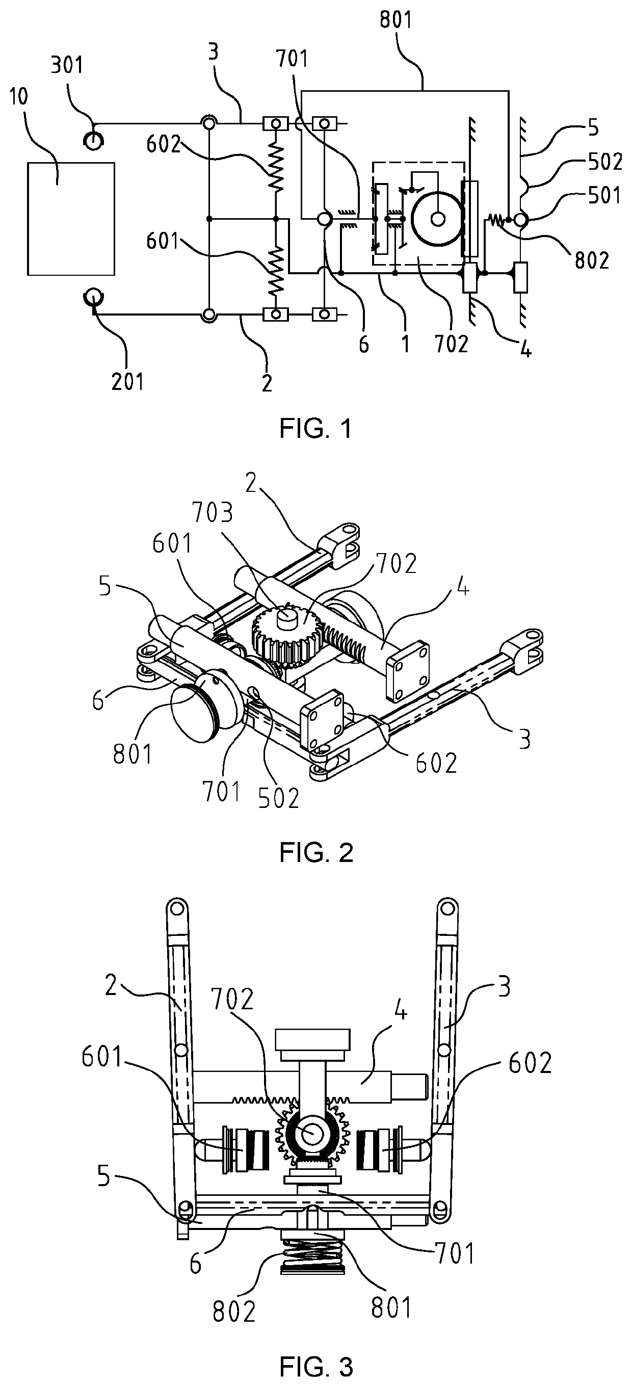
[0046]With reference to FIGS. 1, 2 and 3, an embodiment of the present application provides a follow-up mechanism, comprising a follow-up connector 1, a first unlocking member 2 and a second unlocking member 3 that are located on two sides of the follow-up connector 1 and movably connected to the follow-up connector 1 respectively, a transverse displacement recognition device movably connected to the first unlocking member 2 and the second unlocking member 3, a toothed locking and positioning device mounted on the follow-up connector 1, and two mutually parallel fixation members. The fixation members are denoted as a first fixation member 4 and a second fixation member 5, respectively. The follow-up connector 1 is in sliding fit with the first fixation member 4 and the second fixation member 5, respectively. A first slider 201 is fixedly connected at an end of the first unlocking member 2, and a second slider 301 is fixedly connected at an end of the second unlocking member 3. The f...

embodiment 2

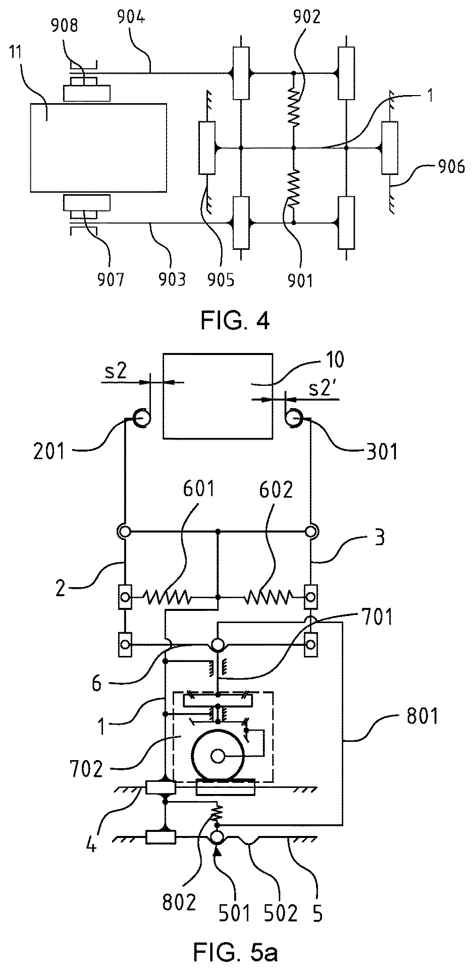
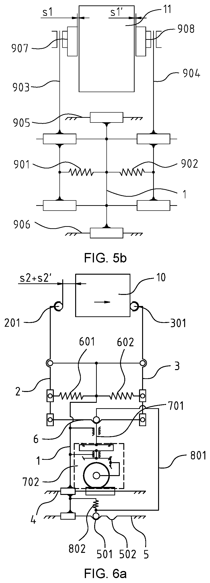
[0075]With reference to FIGS. 1, 2, 3, 18 and 19, another embodiment of the present application provides a follow-up mechanism comprising a follow-up connector 1, a first unlocking member 2 and a second unlocking member 3 that are located on two sides of the follow-up connector 1 and movably connected to the follow-up connector 1 respectively, a transverse displacement recognition device movably connected to the first unlocking member 2 and the second unlocking member 3, a toothed locking and positioning device mounted on the follow-up connector 1, and two mutually parallel fixation members. The fixation members are denoted as a first fixation member 4 and a second fixation member 5, respectively. The follow-up mechanism further comprises an automatic centering device. With reference to FIGS. 4 and 17, the automatic centering device comprises slide portions, balancing elastic members and two mutually parallel fixation members. The slide portions are located on two sides of the follo...


PUM


Abstract

The present application relate to a follow-up mechanism and a brake caliper unit for gauge-changeable bogie, the follow-up mechanism includes a follow-up connector, unlocking members that are located on two sides of the follow-up connector and movably connected to the follow-up connector, a transverse displacement recognition device movably connected to the unlocking members, a toothed locking and positioning device mounted on the follow-up connector, and at least two mutually parallel fixation members; the follow-up connector is in sliding fit with the fixation members, and sliders are fixedly connected at ends of the unlocking members; the toothed locking and positioning device is movably connected to the transverse displacement recognition device and fixation members, respectively; the brake caliper unit comprises a mounting bracket, the follow-up mechanism, and a brake actuator mounted on the mounting bracket, the follow-up mechanism is installed in cooperation with the brake actuator, and the fixation members are fixedly mounted on the mounting bracket. The present application can automatically recognize the orbit change of a train, the follow-up mechanism moves with a wheel by means of its stored elastic force and the unlocking members, and can self-locked at the target gauge position, thus realizing the change in position.

Description

CROSS-REFERENCE TO RELATED APPLICATION[0001]This application is a continuation application of international Application No. PCT / CN2018 / 124309, filed on Dec. 27, 2018, which in turn claims the priority benefits of Chinese Patent Application No. 201810219931.9, filed on Mar. 16, 2018. The contents of the above identified applications are incorporated herein by reference in their entirety.TECHNICAL FIELD[0002]The present application belongs to the technical field of rail vehicle braking, and relates to a brake device for rail vehicles and particularly to a follow-up mechanism and brake caliper unit for a gauge-changeable bogie.BACKGROUND OF THE PRESENT INVENTION[0003]Among the basic brake devices in the field of railway traffic, disc-type brake devices are usually called brake caliper units. The brake caliper units mainly include two structures, i.e., a three-point mounting structure and a compact four-point mounting structure. The above mentioned structures of the brake caliper units ...

Claims


Application Information

Patent Timeline
Patent Type & Authority Patents(United States)
IPC IPC(8): B61H5/00B61H9/00B60T17/22F16D65/00F16D55/00B61F7/00F16D55/224
CPCB61H5/00B60T17/228B61H9/00F16D65/0056B61F7/00F16D55/2245F16D2055/0008B61F5/50F16D55/22B60T17/22
Inventor WANG, ZHENMENG, QINGYUWANG, LINGJUNDAI, XIAOCHAOZHANG, XINWANG, FENGZHOUHUANG, JIANSONGZHANG, FANGLIANGHUANG, SHIWEI
Owner CRRC QINGDAO SIFANG ROLLING STOCK RES INST CO LTD CN
Why Eureka
Try Eureka