Signal processing apparatus and method

a technology of signal processing and processing apparatus, applied in electrical apparatus, multiplex communication, network traffic/resource management, etc., can solve problems such as the difficulty of signal detection of the present system, and achieve the effect of suppressing the reduction of reception sensitivity

Active Publication Date: 2021-12-28
SONY SEMICON SOLUTIONS CORP
View PDF16 Cites 4 Cited by
  • Summary
  • Abstract
  • Description
  • Claims
  • Application Information

AI Technical Summary

Benefits of technology

[0026]The present technology allows signal processing. In addition, the present technology is able to suppress a reduction in reception sensitivity.

Problems solved by technology

Accordingly, a reception signal may sometimes contain an extremely strong interfering wave, and in a case where this happens, a detection of a signal of the present system may become difficult.

Method used


Image

  • Signal processing apparatus and method
  • Signal processing apparatus and method
  • Signal processing apparatus and method

Examples


first embodiment

3. First Embodiment

[0134]

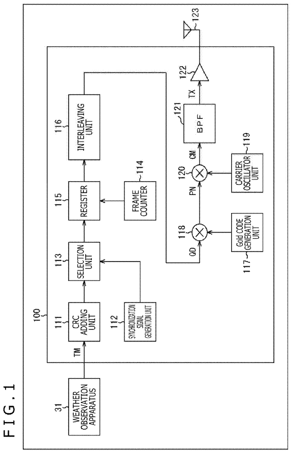
[0135]FIG. 5 is a diagram illustrating a configuration example of primary parts of a reception apparatus according to one embodiment of the signal processing apparatus to which the present technology has been applied. A reception apparatus 200 illustrated in FIG. 5 is an apparatus that receives and demodulates the transmission signal TX transmitted from the transmission apparatus 100 illustrated in FIG. 1 to obtain, for example, the weather observation data (e.g., observation data including atmospheric temperature, sunshine, rainfall, wind direction, wind speed, etc.) or the like. The reception apparatus 200 is installed, for example, in an urban area near a base of a mountain or the like (e.g., in a research facility of a university or the like, or in a facility such as a data center or the like), and receives the wireless signal (i.e., a wireless signal transmitted from a location at a long distance) transmitted from the transmission apparatus 100 installe...

second embodiment

4. Second Embodiment

[0238]

[0239]Note that a configuration of the interference suppression processing unit 221 may be modified as desired, and is not limited to the example illustrated in FIG. 7. FIG. 25 illustrates another example of an equivalent circuit representing a process performed by the interference suppression processing unit 221. In the example illustrated in FIG. 25, the interference suppression processing unit 221 includes, in addition to an approximate replica generation unit 231 and a computation unit 232, a complex low-pass filter (complex LPF 116 KHz) 311, a limiter (±1.5 TL) 312, and a complex low-pass filter (complex LPF 50.8 KHz) 313.

[0240]The complex low-pass filter 311 is a filter for subjecting a reception signal to band limiting such that interfering waves outside of a reception channel are eliminated. This complex low-pass filter 311 is designed to eliminate components that are obviously not related to a signal transmitted from the transmission apparatus 100,...

third embodiment

5. Third Embodiment

[0260]

[0261]FIG. 28 illustrates yet another example of an equivalent circuit representing a process performed by an interference suppression processing unit 221. In the example illustrated in FIG. 28, an approximate replica generation unit 231 of the interference suppression processing unit 221 further includes an amplification unit 341 in addition to the components illustrated in FIG. 25.

[0262]The amplification unit 341 amplifies the amplitude of an output of a complex composition unit 324, that is, the result (i.e., the complex composition result, Q′(t) and I′(t)) of subjecting the phase detection result and the envelope detection result to the complex composition, at a predetermined amplification factor. In this case, the amplification factor has a value less than one. In the case of the example illustrated in FIG. 28, the amplification factor is 0.98. That is, the signal level of the approximate replica signal is reduced. Accordingly, it can be also said that ...


PUM


Abstract

The present technology relates to a signal processing apparatus and method which are able to suppress a reduction in reception sensitivity. A reception signal is compressed so as to have a predetermined signal level or lower, and transmission data transmitted from a transmitter side and included in the reception signal compressed so as to have the signal level or lower is decoded. For example, an approximate replica signal reproducing large amplitude changes of the reception signal is generated, and the approximate replica signal is subtracted from the reception signal to compress the reception signal so as to have the signal level or lower. The present disclosure is applicable to, for example, a signal processing apparatus, a reception apparatus, a transmission / reception apparatus, a communication apparatus, an information processing apparatus, an electronic device, a computer, a program, a storage medium, a system, and so on.

Description

CROSS REFERENCE TO RELATED APPLICATIONS[0001]This application is a U.S. National Phase of International Patent Application No. PCT / JP2018 / 006417 filed on Feb. 22, 2018, which claims priority benefit of Japanese Patent Application No. JP 2017-043812 filed in the Japan Patent Office on Mar. 8, 2017. Each of the above-referenced applications is hereby incorporated herein by reference in its entirety.TECHNICAL FIELD[0002]The present technology relates to a signal processing apparatus and method, and, in particular, to a signal processing apparatus and method which are able to suppress a reduction in reception sensitivity.BACKGROUND ART[0003]In the past, a system for transmitting information from a sensor or the like using, for example, electric waves in a 920 Mz band has been conceived of as a technique for implementing long-distance wireless communication (see, for example, PTL 1). Use of a system described in PTL 1 enables a short time to be set as a maximum continuous transmission ti...

Claims


Application Information

Patent Timeline
Patent Type & Authority Patents(United States)
IPC IPC(8): H04W28/06H04W28/04
CPCH04W28/06H04W28/04H04B1/7097H04J13/0029H04B2201/709718
Inventor KOBAYASHI, SEIJI
Owner SONY SEMICON SOLUTIONS CORP
Why Eureka
Try Eureka