Valve assembly

a valve assembly and valve body technology, applied in the direction of positive displacement liquid engines, piston pumps, liquid fuel engines, etc., can solve the problems of short component lifetime, increased pressure of leaked fluid surrounding the coupling,

Active Publication Date: 2022-01-04
ARTEMIS INTELLIGENT POWER
View PDF17 Cites 0 Cited by
  • Summary
  • Abstract
  • Description
  • Claims
  • Application Information

AI Technical Summary

Benefits of technology

[0006]The working fluid gallery outlet typically fluidly connects to the working fluid gallery in use, i.e., when the valve assembly is installed in the fluid working machine for regulating the flow of working fluid between the working chamber and the working fluid gallery. That is to say, the connector void is typically in fluid communication with the working fluid gallery by way of (e.g. through) the working fluid gallery outlet in use, i.e., when the valve assembly is installed in the fluid working machine for regulating the flow of working fluid between the working chamber and the working fluid gallery. Accordingly, working fluid can typically flow between the connector void and the working fluid gallery. This reduces working fluid pressure cycling in the connector void during operation of the fluid working machine. In particular, if pressure in the connector void begins to increase during operation of the fluid working machine (typically due to leakage of working fluid from the working chamber into the connector void or movement of the connector within the tube), working fluid is typically displaced from the connector void, through the working fluid gallery outlet, and into the working fluid gallery. Similarly, if pressure in the connector void begins to decrease during operation of the fluid working machine (typically due to movement of the connector within the tube), working fluid is drawn into the connector void from the working fluid gallery through the working fluid gallery outlet. By reducing working fluid pressure cycling in the connector void, fatigue failure of the valve assembly components becomes less likely and the component lifetimes are increased.
[0010]The tube may be a sleeve which extends around a portion of the connector. The sleeve may protrude beyond a face of a fluid gallery bulkhead. The sleeve and connector may be fitted to one another (e.g. an internal diameter of the sleeve and an external diameter of the connector may be selected) such that the sleeve fits around the connector while still providing a connector void between the connector and said sleeve, and such that the required flow rate and lack of frictional resistance is maintained during a pressure-on event). The sleeve may have one or more external faces which are exposed to fluid in a surrounding fluid gallery when in use. Fluid gallery pressure acting on the external faces of the sleeve typically acts so as to cause the sleeve to deflect inwards towards the connector during pressure-on. Deflection of the sleeve towards the connector acts as a seal to reduce leakage of working fluid from the working chamber (through the first connector guide clearance along the connector) to the connector void region. The connector void may be a void provided between a portion of the connector and the sleeve.
[0014]Additional radial clearance between the connector and the tube may be provided by selective reduction in the diameter of the connector, for example by milling or otherwise machining the connector to reduce its diameter over a portion, typically between the bottom guide portion and upper guide portion, such as to provide a greater area to the annular cross section of the connector void, so as to allow for greater flow rates and reduced viscous friction between the connector and the tube.
[0035]It may be that the first connector guide comprises a tube portion which extends away from a side of the fluid gallery wall which faces towards the working chamber, in use, such that an external wall of the tube portion is exposed to working chamber pressure. It may be that the tube portion is internally dimensioned to fit around the connector so that working chamber pressure during pressure-on (i.e., when in use) acts on the external wall of the tube portion to cause said external wall to deflect towards the connector so as to restrict leakage of fluid from the working chamber, through the clearance along the connector, into the connector void.
[0036]It may be that at least a portion of the connector extends at least part-way through the fluid gallery wall. It may be that the fit between the connector and at least a portion of the fluid gallery wall provides a close running or sliding fit.
[0040]It may be that the armature comprises one or more armature fluid passages. The one or more armature fluid passages may extend (e.g. axially) through the armature. The one or more armature fluid passages are typically in fluid communication with the connector void and the armature void. This typically permits fluid to flow between the armature void and the connector void by way of the one or more armature fluid passages. Pressure build-up due to, for example, compression of fluid in the armature void on movement of the armature within the armature void is thereby typically reduced.

Problems solved by technology

The pressure of leaked fluid surrounding the couplings also tends to increase gradually during operation of the valve.
Increased fluid pressure and, particularly, cycling of fluid pressure around the coupling typically require components to be manufactured from high-strength and highly fatigue-resistant materials otherwise fatigue failure is common and component lifetimes are short.

Method used


Image

  • Valve assembly
  • Valve assembly
  • Valve assembly

Examples


Embodiment Construction

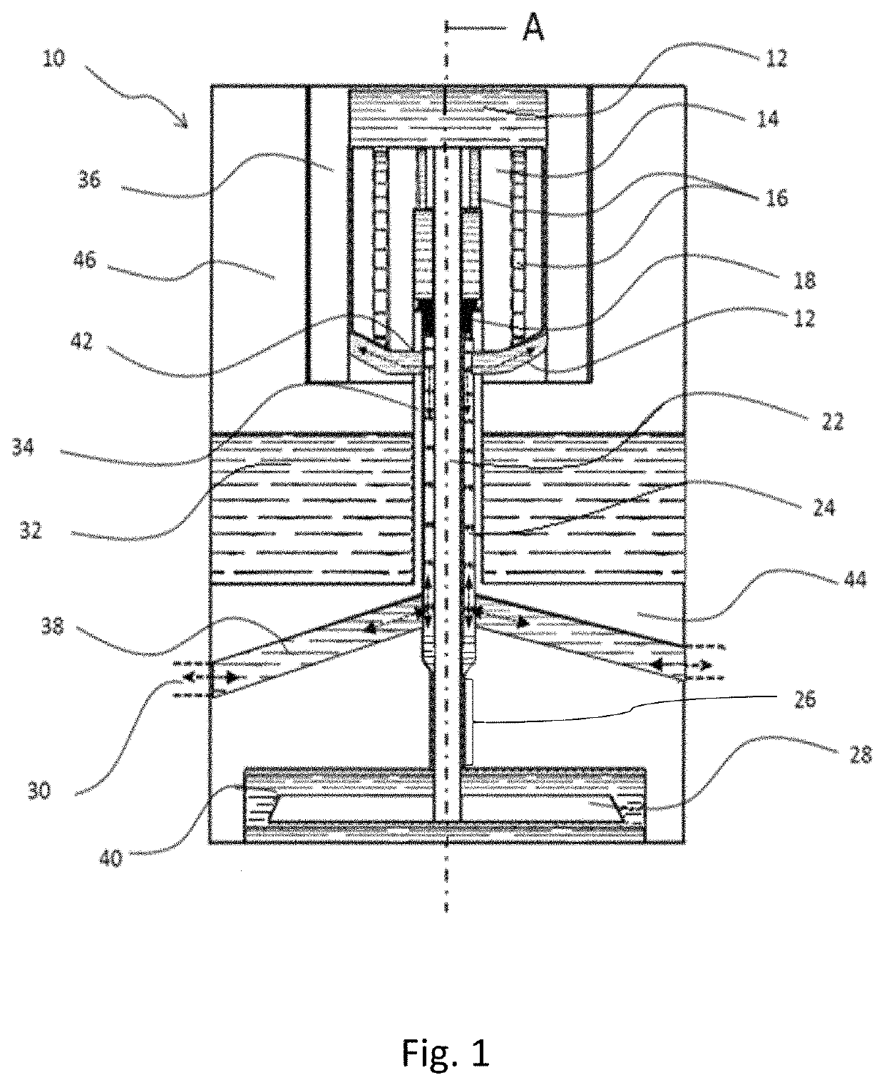
[0054]FIG. 1 is a schematic cross section through an example embodiment of a valve assembly 10. The valve assembly has an annular valve member 28 (the valve member) fixedly mounted to a cylindrical, solid connecting rod 22 (the connector) which extends through and is fixedly attached to an armature 14 (the armature). The valve member, connecting rod and armature are arranged along a valve assembly axis A. The valve member comprises two sealing lines.

[0055]The valve assembly also has a valve capsule 46 and a pressure bulkhead 44 (the fluid gallery wall or base component). The valve capsule surrounds a solenoid coil 36 (the actuator) which is provided around the armature 14. The armature does not fill all of the space surrounded by the solenoid coil such that an armature void is provided between the armature, the solenoid coil and interior walls of the valve capsule. The pressure bulkhead forms a valve member void 40, which surrounds the valve member 28 and one or more valve seats for...


PUM


Abstract

A valve assembly for regulating the flow of working fluid between a working chamber of a fluid working machine and a working fluid gallery comprises: a valve comprising a valve member and one or more cooperating valve seats; an actuator actuatable to apply a force to urge the valve member away from or towards the one or more valve seats; and a coupling between the actuator and the valve member. The coupling comprises a connector located at least partially within a tube. A connector void provided between at least a portion of the connector and the tube is in fluid communication with a working fluid gallery outlet.

Description

[0001]The present application is a National Phase of International Application Number PCT / GB2018 / 052466, filed Aug. 31, 2018, which claims priority to Great Britain Application No. 1714415.5, filed Sep. 7, 2017, and both are hereby incorporated by reference in their entirety into the present application.FIELD OF THE INVENTION[0002]The invention relates to valve assemblies for regulating the flow of working fluid between a working chamber of a fluid working machine and a working fluid gallery, and fluid working machines comprising a working chamber, a working fluid gallery and such valve assemblies.BACKGROUND TO THE INVENTION[0003]Valve assemblies for regulating the flow of working fluid between a working chamber of a fluid working machine and a working fluid gallery are known. In some such valve assemblies, the movement of a valve member towards or away from a valve seat is actuated by an actuator coupled to the valve member by a coupling. Fluid leakage in working fluid working mach...

Claims


Application Information

Patent Timeline
Patent Type & Authority Patents(United States)
IPC IPC(8): F16K31/06F04B7/00F04B1/053F04B53/10
CPCF16K31/0655F04B7/0076F04B1/053F04B53/10F16K31/0651F16K31/0675F04B1/0465F04B53/102F03C1/0444F03C1/053F16K31/0624
Inventor CHANG, MUN KEONGDODSON, HENRYEILERS, JENS
Owner ARTEMIS INTELLIGENT POWER
Why Eureka
Try Eureka