Dental instrument hanger
a technology for dental instruments and hangers, applied in dental chairs, medical science, surgery, etc., can solve problems such as identification failures, and achieve the effect of reducing identification failures
- Summary
- Abstract
- Description
- Claims
- Application Information
AI Technical Summary
Benefits of technology
Problems solved by technology
Method used
Image

Examples
first embodiment
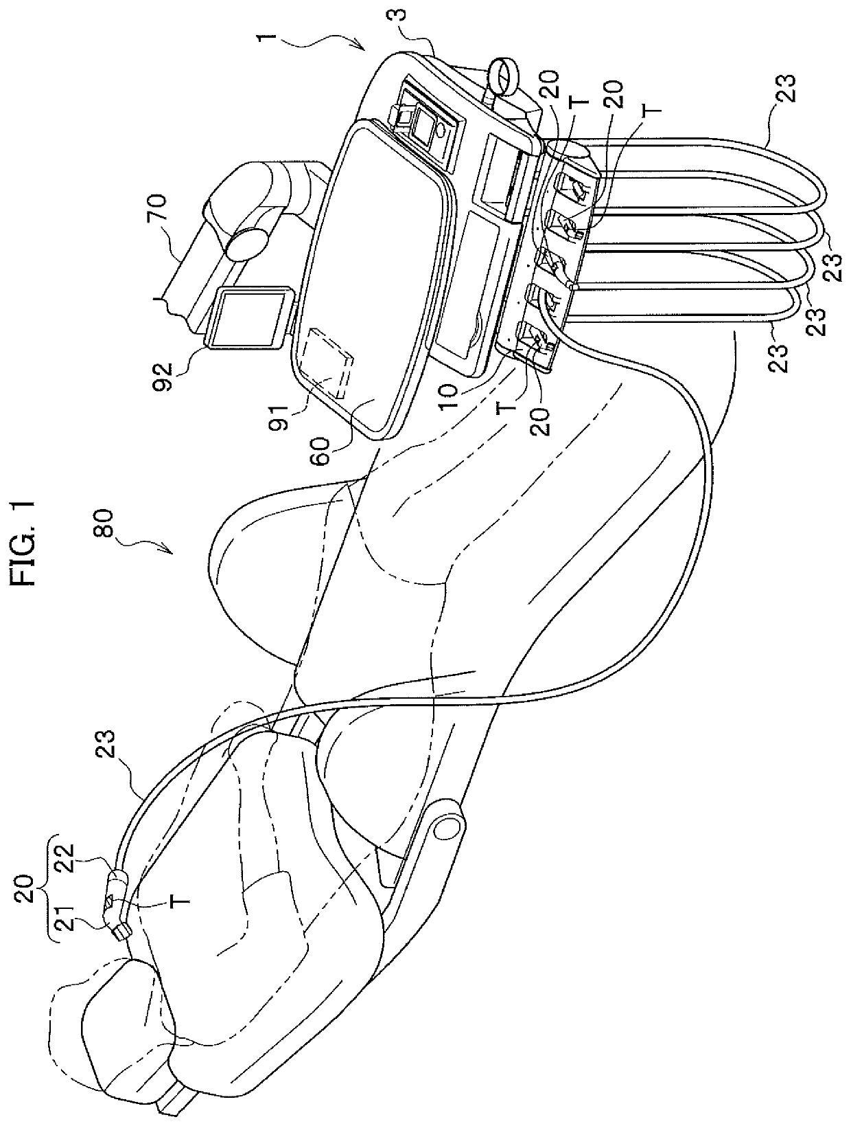
[0029]As shown in FIG. 1, a dental instrument hanger 1 includes a unit body 3 and a hanger unit 10 provided in the unit body 3. In this example, the dental instrument hanger 1 is supported by an arm unit 70. Note that the arm unit 70 is connected to a base of a patient chair 80 and other dental treatment facilities, although a portion of the arm unit 70 closer to the base end is not illustrated. Here, dental treatment equipment includes such as an automatic water faucet, a spittoon, a shadowless lamp, and a vacuum system, but those are not illustrated nor described.
[0030]In addition, the dental instrument hanger 1 usually includes an instrument hanger for a doctor and an instrument hanger for an assistant, but in the present embodiment, an instrument hanger for a doctor will be described as an example. Additionally, a description will be given in the present embodiment of the dental instrument hanger 1 supported by the arm unit 70, but the present invention is not limited to this ty...
second embodiment
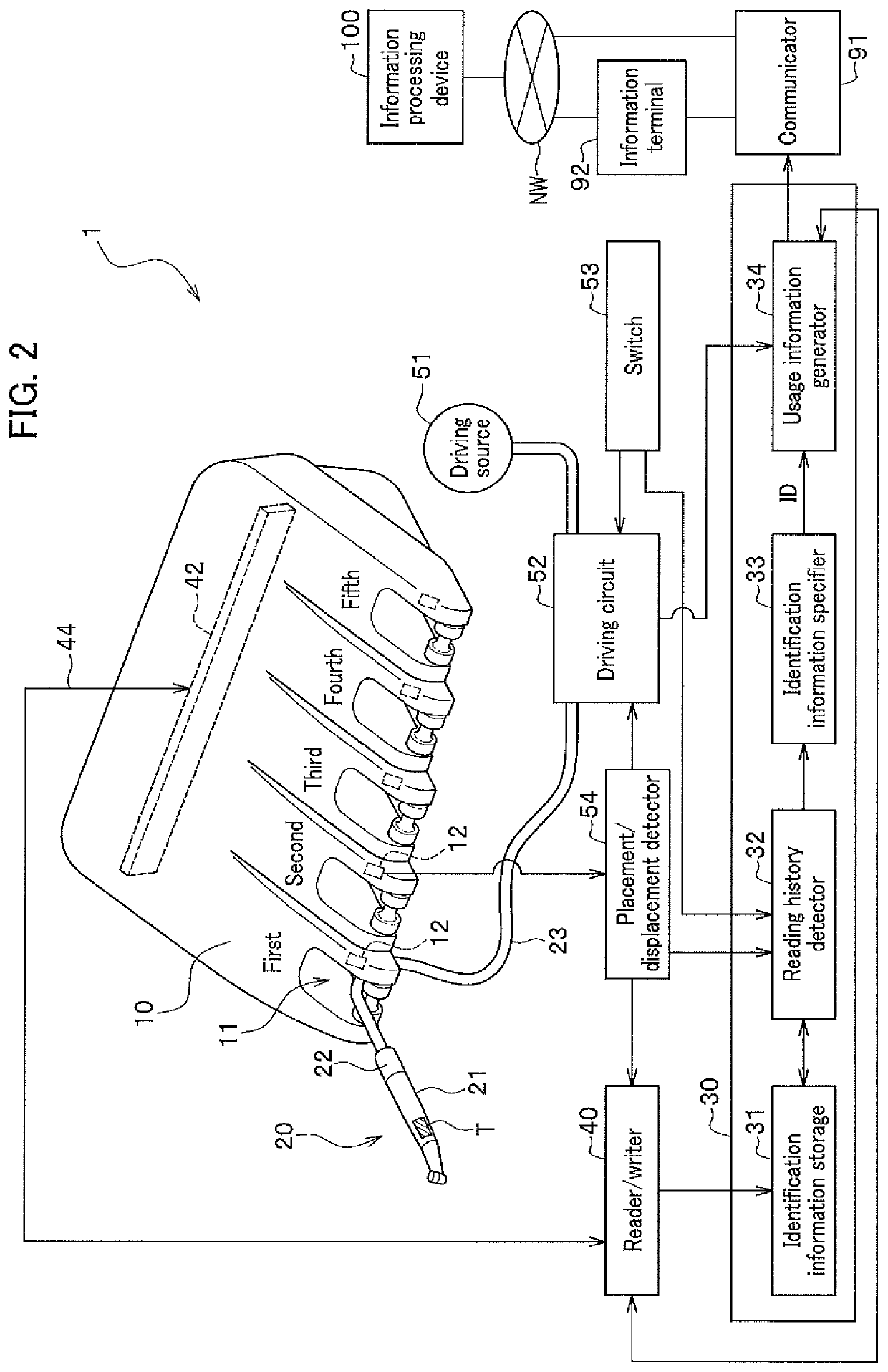
[0083]A description will be given of a dental instrument hanger 1B according to a second embodiment of the present invention, with reference to FIG. 5. Hereinbelow, the same components as those of the dental instrument hanger 1 according to the first embodiment are denoted by the same reference numerals, and descriptions thereof are omitted. The dental instrument hanger 1B includes antennas 42, each connected to the reader / writer 40, for the respective holders 11 in a hanger unit 10B. That is, the first holder 11 is provided for the first antenna 42, and the second holder 11 is provided for the second antenna 42. These small antennas 42 are built in the hanger unit 10B.
[0084]The present embodiment is designed to use the hanger sensor 12 and the antenna 42 for each holder 11 to specify the holder 11 in the hanger unit 10 from which the instrument 20 has been displaced. Then, the placement / displacement detector 54 is free from notifying the reading history detector 32 of the instrumen...
first modification
of Second Embodiment
[0088]The second embodiment may also be modified so that every antenna 42 of the reader / writer 40 periodically reads identification information (ID) from the nearby wireless tag T. In this first modification, the hanger sensor 12 and the placement / displacement detector 54 are excluded. In addition, the reading history detector 32 periodically refers to the identification information storage 31 at a predetermined frequency, not only at the time of the driving instruction to drive the instrument 20 being inputted, to detect the latest reading history for the identification information of the wireless tag T attached to every instrument 20. Note that other parts are the same as those in FIG. 5, and therefore no drawing is provided for the present first modification.
[0089]Further, in the first modification, when the instrument 20 is displaced from the third holder 3, for instance, to the outside of the hanger unit 10, the wireless tag T attached to the corresponding i...
PUM
 Abstract
Description
Claims
Application Information
 - R&D
- Intellectual Property
- Life Sciences
- Materials
- Tech Scout
- Unparalleled Data Quality
- Higher Quality Content
- 60% Fewer Hallucinations
Browse by: Latest US Patents, China's latest patents, Technical Efficacy Thesaurus, Application Domain, Technology Topic, Popular Technical Reports.
© 2025 PatSnap. All rights reserved.Legal|Privacy policy|Modern Slavery Act Transparency Statement|Sitemap|About US| Contact US: help@patsnap.com