Projection apparatus illuminating with cloud effect

a projection apparatus and cloud effect technology, applied in the field of projection lamps, can solve the problems of affecting the user experience and efficiency affecting the energy saving and environmental protection capabilities of the light source, etc., and achieve the effects of enhancing user experience, reducing or avoiding light leakage, and improving light utilization rate of the light sour

Active Publication Date: 2022-01-11
XU LONGCAI
View PDF6 Cites 4 Cited by
  • Summary
  • Abstract
  • Description
  • Claims
  • Application Information

AI Technical Summary

Benefits of technology

[0007]Considering the defects of prior art, this invention seeks to provide a projected apparatus that illuminates a cloud effect that can realize dynamic changes. The projected apparatus can improve the light utilization rate of the light source to a greater extent, effectively reduce or avoid light leaking from the projection source to enhance user experience.

Problems solved by technology

If the housing around the projection is thin or lightly colored, or there are gaps due to a loose-fitting assembly, light will leak out of the device, marring the user experience and efficiency of the light source, undermining its energy saving and environmental protection capabilities.

Method used


Image

  • Projection apparatus illuminating with cloud effect
  • Projection apparatus illuminating with cloud effect
  • Projection apparatus illuminating with cloud effect

Examples


first embodiment

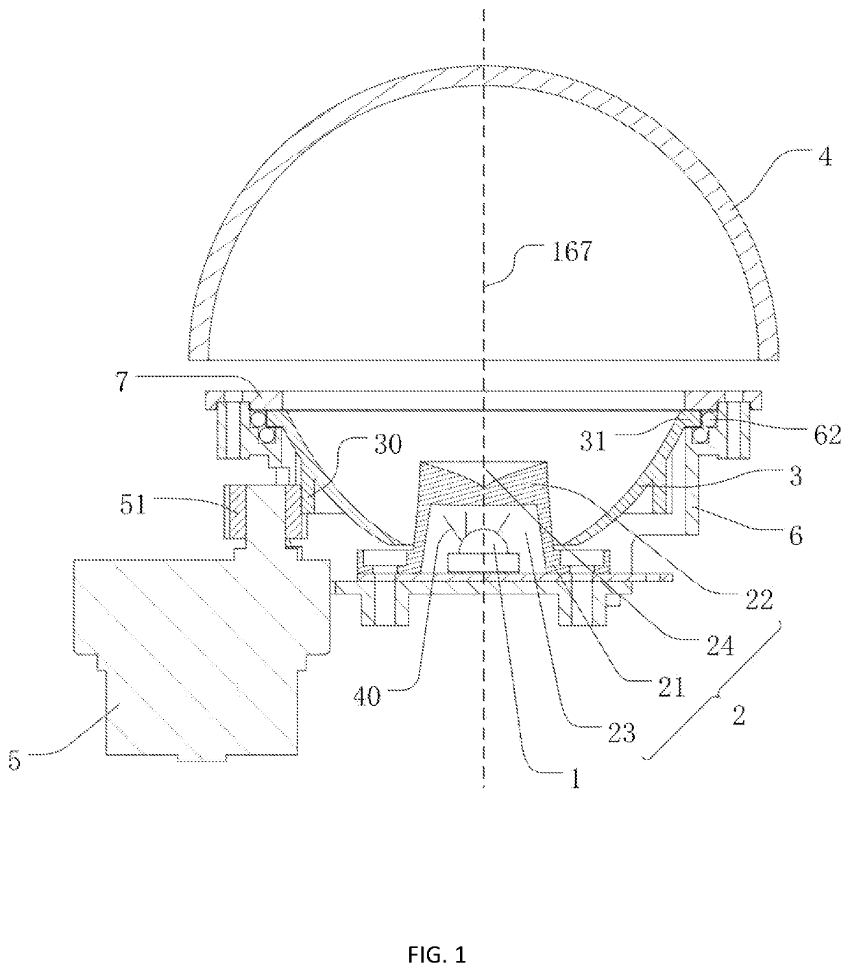
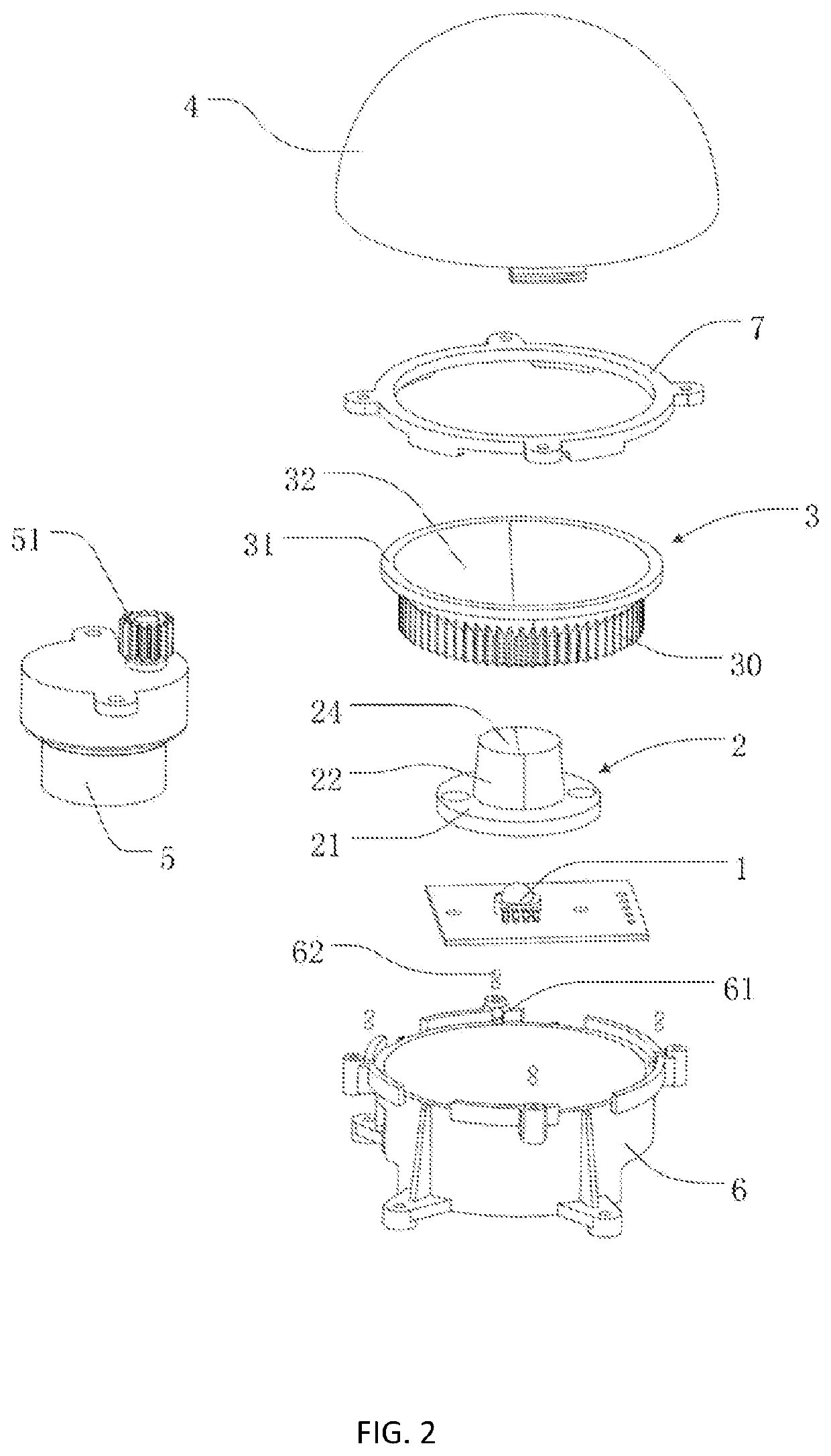
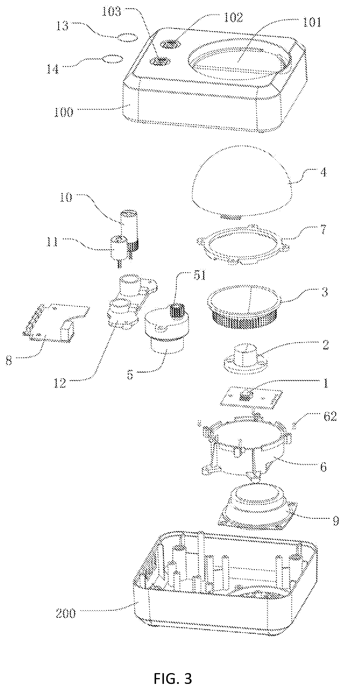
[0052]FIGS. 1-4 illustrate the present invention. A projection apparatus comprises a first projection component, which has a first light source 1, a light conductor 2 placed upon the first light source 1, a rotating reflective bowl 3 with a through opening 126 at the bottom thereof and a transparent cover 4 set with a light refracting surface 127. The first light source 1 and the light conductor 2 form a light source component 123. The transparent cover 4 is located above the reflective bowl 3, such that the reflective bowl 3 is located between the transparent cover 4 and the light source component 123. The first light 40 emitted from the first light source 1 is directed by the light conductor 2 to illuminate the reflective bowl 3 and is reflected and then projected through the transparent cover 4 onto a surface to present a cloud effect. The light source component 123 is electrically connected to a control circuit board 8.

[0053]The projection apparatus further comprises a driving m...

second embodiment

[0069]FIGS. 5-8 show a second embodiment of the present invention. the projection apparatus is distinguished from the first embodiment by the following characteristics.

[0070]The first projection component of the second embodiment comprises an annular rotating seat connected to the housing section 100, wherein the transparent cover 4 is fixed on the annular rotating seat, and the driving gear 51 on the driving motor 5 engages with an outer gear 160 arranged on the annular rotating seat. The driving motor 5 drives the transparent cover 4 to rotate through driving the annular rotating seat.

[0071]Referring to FIG. 6, the annular rotating seat includes a first rotary seat 16 and a second rotary seat 17. The first rotary seat 16 has an outer gear 160 which engages the driving gear 51 mounted on the rotor shaft of the driving motor 5. The first rotary seat 16 is connected to and can be released from the second rotary seat 17. The second rotary seat 17 is provided with a protruding holding ...

third embodiment

[0076]FIGS. 9-12 show a third embodiment of the present invention. the projection apparatus is distinguished from the first embodiment by the following characteristics.

[0077]The first projection component of the third embodiment comprises an annular lamp holder 18, and the first light source 1 is fixed on the annular lamp holder 18. The first light source 1 and the annular lamp holder 18 constitute the light source component, wherein the light source component is located between the transparent cover 4 and the reflective bowl 3.

[0078]Referring to FIGS. 9-10, the annular lamp holder 18 comprises a positioning portion 181 and an extension portion 182 formed from the positioning portion 181 towards the direction near the central axis of the annular lamp holder 18 and extending upward in an inclined direction. The first light source 1 is fixed on the inner surface of the extension portion 182, and the light emitted by the first light source 1 is illuminated on the reflective surface 32 ...


PUM


Abstract

A projection apparatus comprises a housing with a projection opening, a light source component, a reflective bowl and a driving motor in the housing, and a transparent cover is mounted on the housing and protrudes upwardly out of the projection opening. The light emitted by the light source component is illuminated on the reflective surface, and then the light passes through the transparent cover after being reflected. The light source component, the reflective bowl and the transparent cover can project to produce a cloud effect.

Description

RELATED APPLICATIONS[0001]This application is the continuation application to U.S. patent application Ser. No. 17 / 334,266, filed on May 28, 2021, claiming priority to CN202120325517.3, CN202120323204.4, CN202120325394.3 and CN202120325395.8, which are all filed on Feb. 3, 2021, the disclosures of which are incorporated herein by reference in their entirety.FIELD OF INVENTION[0002]The disclosure relates generally to the technical field of projection lamps. The disclosure relates specifically to a projection apparatus illuminating with cloud effect.BACKGROUND OF THE INVENTION[0003]Projection lamps that create ambient light are generally used in theaters, studios, bars, discos, and other venues that required effects for entertainment purposes. With the growing demand for home entertainment or creating specific projections of ambient light, the portable, compact, energy-saving, and multi-functional ambient projection lamp, that also functions as a decorative lamp, is more popular today....

Claims


Application Information

Patent Timeline
Patent Type & Authority Patents(United States)
IPC IPC(8): F21S10/06F21V5/04F21V7/04F21V7/10F21V3/02
CPCF21S10/063F21V3/02F21V5/04F21V7/045F21V7/10F21V7/04F21V7/22F21V14/04F21W2121/008
Inventor XU, LONGCAI
Owner XU LONGCAI
Why Eureka
Try Eureka