
System and method for harvesting autologous adipose tissue

a technology of autologous adipose tissue and harvesting method, which is applied in the field of medical aesthetics, can solve the problems of cumbersome and expensive known techniques, unacceptably high rejection rate, and complicated and expensive costs

Active Publication Date: 2022-01-25
PELED OMER +1
View PDF22 Cites 0 Cited by
  • Summary
  • Abstract
  • Description
  • Claims
  • Application Information

AI Technical Summary

Benefits of technology

The patent describes a triple-chambered container for separating and collecting different components of adipose tissue. The container has three chambers that can be selectively moved to receive and discharge fluids with each other. The container can be used to withdraw human adipose tissue, separate it into different components, and reintroduce specific components into the human body. The method includes centrifuging the container to separate the adipose tissue into four components, and then moving them to their designated chambers for further manipulation and use. The technical effects of this invention include improved efficiency and accuracy in the separation and collection of adipose tissue components.

Problems solved by technology

Known techniques, however, are cumbersome, complicated and expensive.
Further, with existing techniques, the need to remove and move fat components during the harvesting and filtering process may cause contamination of the fat components and thus medical complications to the patient.
In addition, it has been found that in existing autologous fat removal systems, methods and devices that the rejection rate may be unacceptably high.
One existing problem is how to structure a device and its method of use to separate out the several fat components and to mix the ASC material with the adipose tissue efficiently and without risking contamination.

Method used


Image

  • System and method for harvesting autologous adipose tissue
  • System and method for harvesting autologous adipose tissue
  • System and method for harvesting autologous adipose tissue

Examples


Embodiment Construction

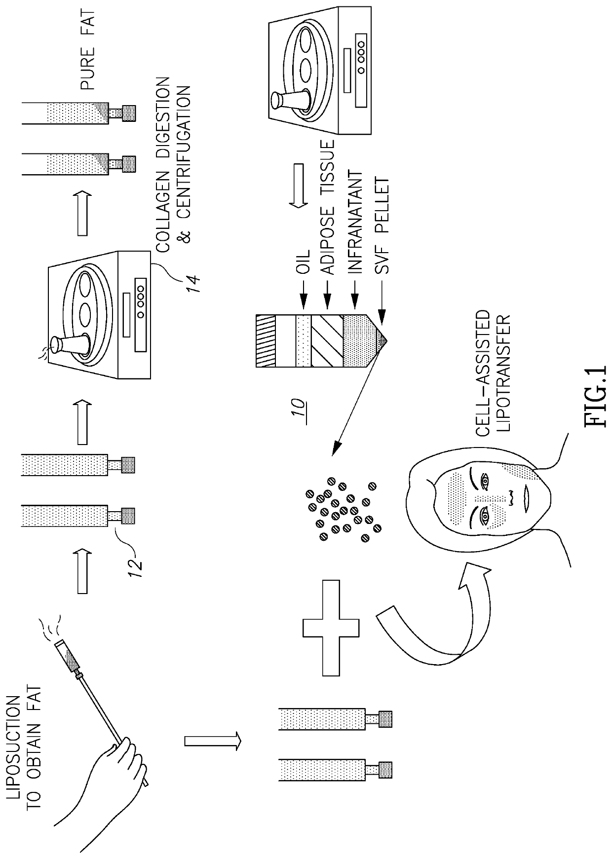
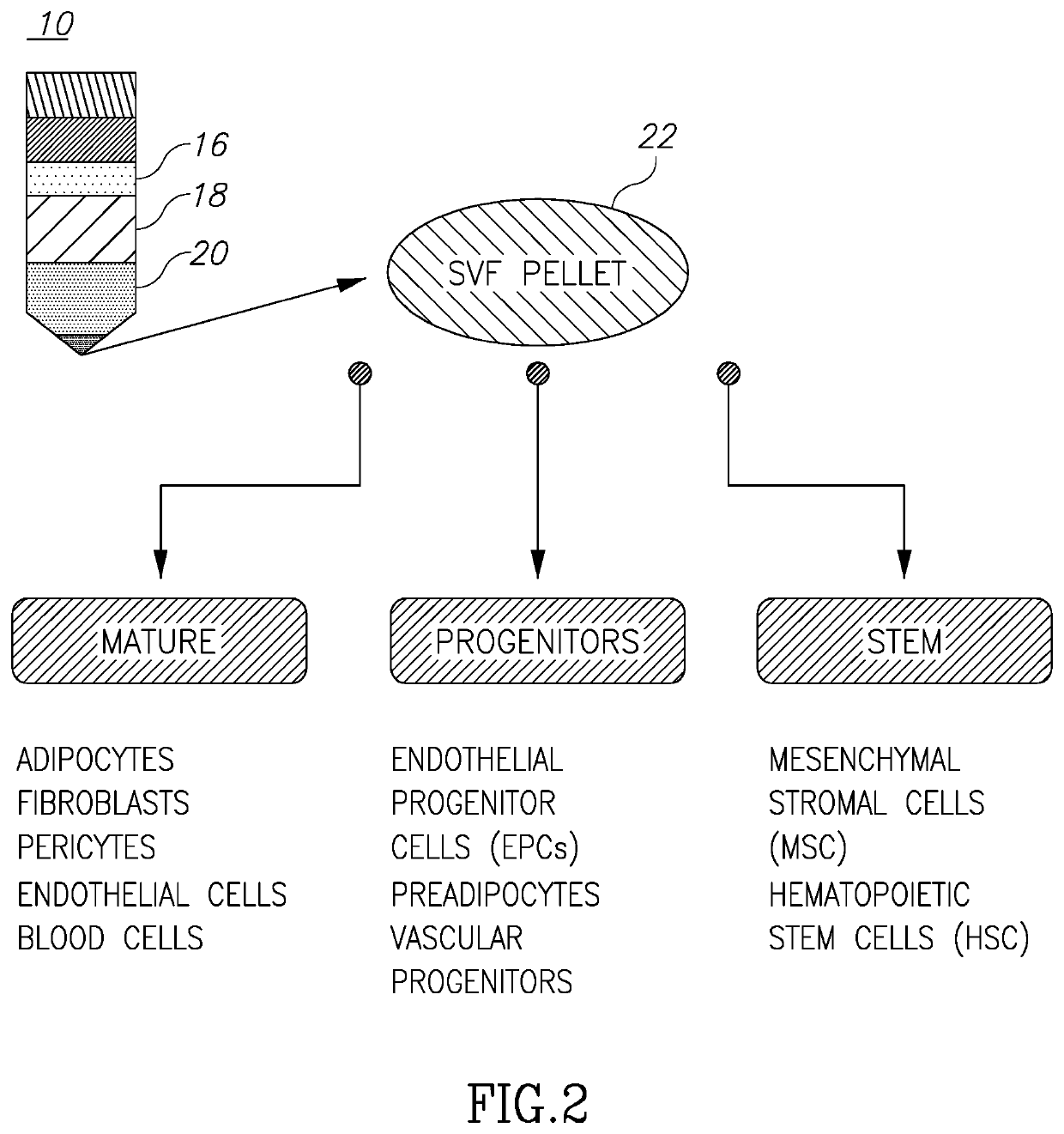
[0034]Turning now to FIGS. 1 and 2, these figures (taken from the above-cited Tan et al. article) illustrate the general known process of harvesting and filtering adipose tissue and are self-explanatory. What is significant to note is the illustrated levels of material 10 shown in those figures. This separation of components comes about after centrifugation of the tubes 12 in the centrifuge 14. Of these materials, the desired reinjected material is a mix of the purified components which are located at levels 18 (the adipose tissue) and 22 (the SVF pellet or adipose-derived stem cells), although sometimes only the adipose tissue separation material may be desirable. The problem, of course, is how to separate the desirable components, such as 18 and 22, from the not-needed components like 16 (oils and lipids) and 20 (infranatant), and not allowing intermixing of desirable and not-needed components, all within an environment so as to prevent contamination.

[0035]Turning now to the opera...


PUM

PropertyMeasurementUnit
volumeaaaaaaaaaa
areaaaaaaaaaaa
structureaaaaaaaaaa

Abstract

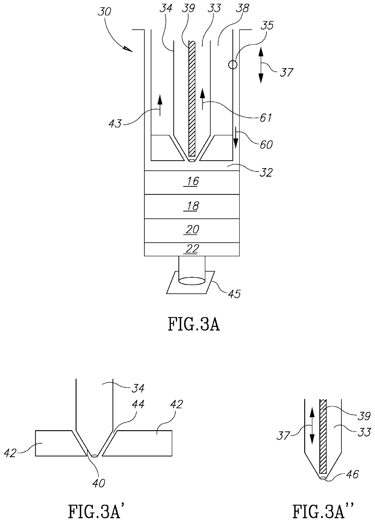
A triple-chambered container includes: a main container body with a first chamber which has an opening at its distal end; a main barrel formed and movable longitudinally within the first chamber, the main barrel defining therein a second chamber for receiving fluids, the main barrel further having an apertured stopper at its distal end; a second barrel formed within the main barrel, the second barrel defining a third chamber for receiving fluids, the second barrel being movable longitudinally within and with respect to the main barrel, the second barrel having a distal end which is engageable and disengageable with the apertured stopper; a shaft adapted to fit within the second barrel, the shaft being movable longitudinally within and with respect to the second barrel, the shaft having a distal end which is engageable and disengageable with an aperture in the second barrel; a device for controlling engaging and disengaging of the distal end of the shaft with the aperture of the second barrel. The first chamber, the second chamber and the third chamber may be selectively moved to receive and discharge fluids with respect to one another.

Description

RELATED APPLICATIONS[0001]This application is related to and claims priority to U.S. provisional application Ser. No. 62 / 623,385, filed Jan. 29, 2018, the entire contents of which is herein incorporated by reference.BACKGROUND OF THE PRESENT INVENTION[0002]In the medical aesthetics field, many techniques are known and practiced to lessen skin tissue imperfections such as wrinkles and sagging skin, particularly in the facial areas. Many of these involve chemical treatments, such as chemical peels, or the use of electromagnetic energy, such as lasers, or even the introduction of somewhat poisonous materials such as Botox® which may be injected into the skin to “plump up” that area of the skin tissue.[0003]It is also known to harvest, filter and inject autologous adipose tissue from one portion of the body and to reinject the filtered fat into a desired area such as in the area of wrinkles or sagging tissue. The benefit of using this autologous fat is that the probability of rejection ...

Claims


Application Information

Patent Timeline
Patent Type & Authority Patents(United States)
IPC IPC(8): A61M1/00A61M5/19A61L27/36A61L27/38
CPCA61L27/3691A61L27/3804A61L27/3834A61M1/0001A61M5/19A61M2202/08A61M1/67A61M1/88A61M1/895A61M1/892A61M1/60
Inventor PELED, OMERMIRABITO, A. JASON
Owner PELED OMER
Learn More