Chain tensioner

a chain tensioner and chain technology, applied in the direction of belts/chains/gearrings, mechanical instruments, belts/chains/gearrings, etc., can solve the problems of sprocket teeth falling and/or skipping, and achieve the effect of reliable and stable manner, smooth movement, and quick absorption of chain looseness

Active Publication Date: 2022-01-25
NTN CORP
View PDF23 Cites 0 Cited by
  • Summary
  • Abstract
  • Description
  • Claims
  • Application Information

AI Technical Summary

Benefits of technology

[0024]For the chain tensioner of the present invention, since the protruding-side flank of the internal thread on the inner periphery of the plunger is a rolled surface having a surface roughness smaller than Ra 1.0 μm, the plunger and the screw rod more smoothly slide relative to each other between the protruding-side flank of the internal thread on the inner periphery of the plunger, and the protruding-side flank of the external thread on the outer periphery of the screw rod. Therefore, the screw rod and the plunger are capable of smoothly moving relative to each other in the direction in which the plunger protrudes from the cylinder, namely, the plunger is

Problems solved by technology

At this time, if, according to the tension of the chain, the plunger moves to a large degree in the direction in which the plunger is pushed into

Method used


Image

  • Chain tensioner
  • Chain tensioner
  • Chain tensioner

Examples


Embodiment Construction

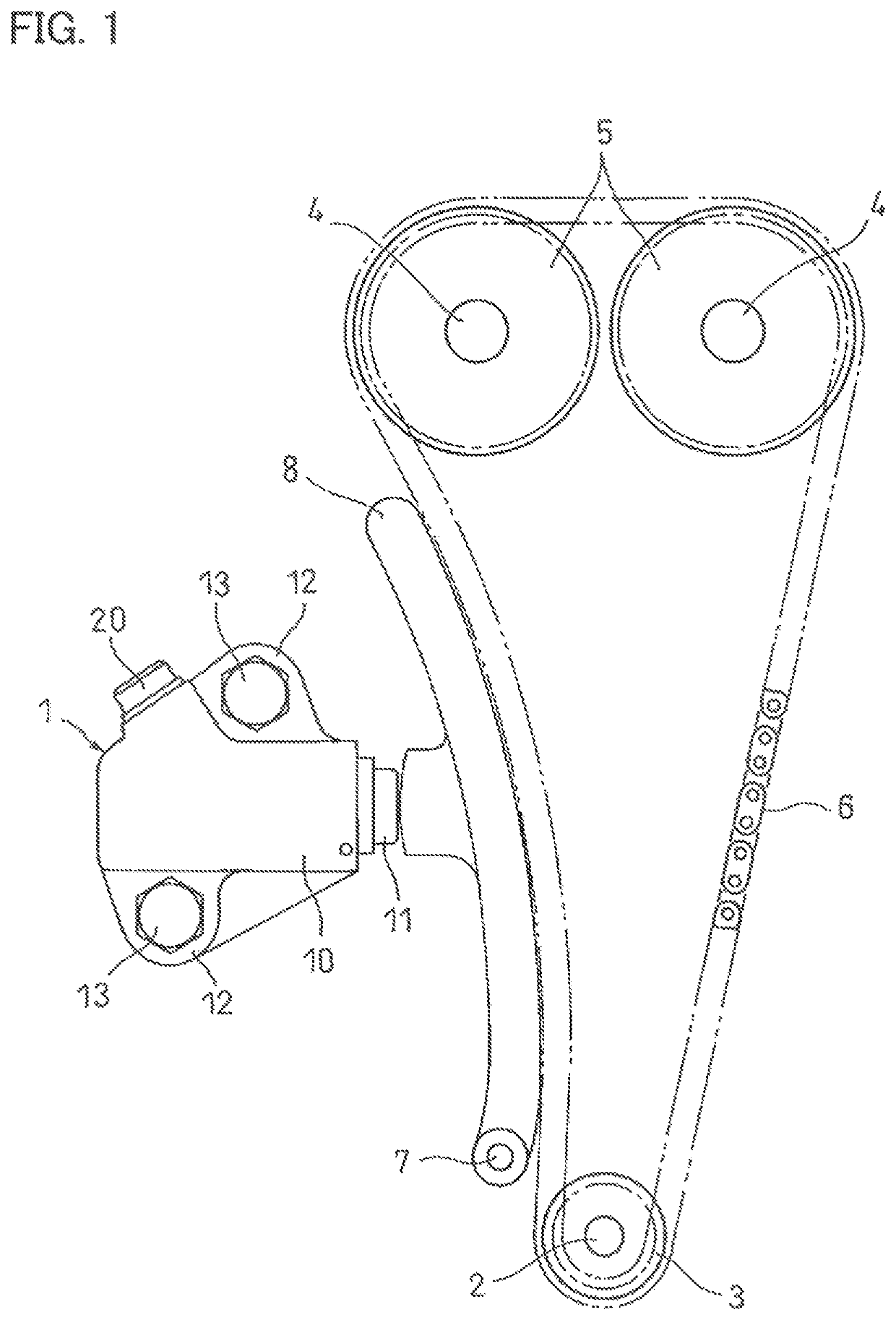
[0034]FIG. 1 illustrates a chain transmission device in which a chain tensioner 1 embodying the present invention is used. This chain transmission device includes a sprocket 3 fixed to the crankshaft 2 of an engine; sprockets 5 fixed to respective camshafts 4; and a chain 6 through which the sprocket 3 is coupled to the sprockets 5. The rotation of the crankshaft 2 is transmitted to the camshafts 4 by the chain 6 so as to rotate the camshafts 4, thereby opening and closing the valves (not shown) of the combustion chambers of the engine.

[0035]A chain guide 8 supported to be pivotable about a fulcrum shaft 7 is in contact with the chain 6. The chain tensioner 1 presses the chain 6 through the chain guide 8.

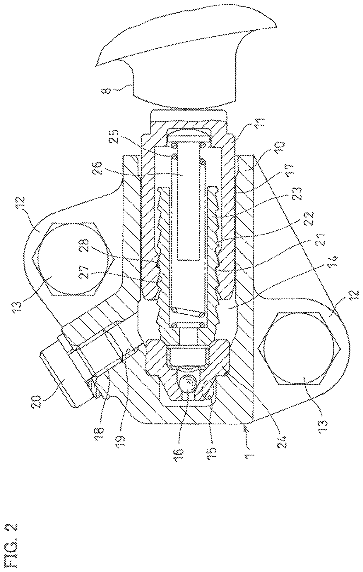
[0036]As illustrated in FIG. 2, the chain tensioner 1 includes a tubular cylinder 10 having a bottom; and a plunger 11 axially slidably inserted in the cylinder 10. The cylinder 10 is made of an aluminum alloy, and fixed to a side surface of an engine block by tightening bolts 13, r...


PUM


Abstract

A chain tensioner is formed with internal threads each including a push-in-side flank, a protruding-side flank, and a thread top face. The push-in-side flank has a flank angle which is larger than a flank angle of the protruding-side flank. The push-in-side flank and the protruding-side flank are rolled surfaces formed by rolling, and have a surface roughness smaller than Ra 1.0 μm. Each internal thread further includes, at a position at which the protruding-side flank intersects with the thread top face, a chamfer configured to receive a bulge resulting from excess materials pushed out from the protruding-side flank during formation of the internal thread by rolling.

Description

TECHNICAL FIELD[0001]The present invention relates to a chain tensioner used to maintain the tension of a timing chain for driving the camshafts of an automobile engine.BACKGROUND ART[0002]In automobile engines, generally, the rotation of the crankshaft is transmitted to the camshafts by a timing chain (hereinafter simply referred to as the “chain”) to rotate the camshafts, thereby opening and closing the valves of the combustion chambers. In order to maintain the tension of the chain within a suitable range, a tension adjusting device is frequently used which comprises a chain guide pivotable about a fulcrum shaft, and a chain tensioner that presses the chain through the chain guide.[0003]As the chain tensioner mounted to the tension adjusting device, a chain tensioner is known which includes a tubular cylinder having a bottom, and a plunger axially slidably inserted in the cylinder (e.g., see the below-identified Patent Document 1).[0004]This chain tensioner is configured such tha...

Claims


Application Information

Patent Timeline
IPC IPC(8): F16H7/08
CPCF16H7/0848F16H2007/0806F16H2007/0812F16H2007/0842F16H2007/0857F16H2007/0872F16H2007/0891F16H7/08
Inventor ONIMARU, KOUICHIMAENO, EIJI
Owner NTN CORP
Why Eureka
Try Eureka