
Low profile remote and wall plate apparatus

a low-profile, remote control technology, applied in the direction of machine supports, securing devices, stands/trestles, etc., can solve the problems of remotes being easily lost or misplaced, conventional remote control technology lacks the capability to control new electronic devices, and the remotes themselves as well as their holders are aesthetically unappealing, etc., to achieve easy removal and replacement, minimal effort, and easy dislodge

Active Publication Date: 2022-02-01
CURRENT PROD CORP
View PDF19 Cites 0 Cited by
  • Summary
  • Abstract
  • Description
  • Claims
  • Application Information

AI Technical Summary

Benefits of technology

The system provides a user-friendly, aesthetically pleasing, and efficient means of controlling window coverings and other devices, ensuring easy installation and removal without damaging surfaces, while maintaining a sleek appearance and minimizing parts for simplicity and cost-effectiveness.

Problems solved by technology

While the capability, range, durability and functionality of remote controls have improved over time, substantial deficiencies still exist in the art.
Namely, remotes are often lost or misplaced because there is no convenient area to place or hold conventional remotes.
Another deficiency with current remote technology is that conventional remote control technology lacks the capability to control new electronic devices, such as new motorized window coverings, in a manner that suits the ever increasing demands of the consumer, and particularly newer generations of consumers.
Another deficiency with current remote control technology is that the remotes themselves as well as their holders are aesthetically unappealing.
Another deficiency with current remote control technology is that their holders are unnecessarily difficult or time consuming to install as well as being unnecessarily permanent once installed.
While the motorization of window coverings has provided certain advantages, one deficiency is that conventional remote control technology lacks convenient, easy to install, usable, functional and aesthetically pleasing ways for the remotes to be installed and held in place and accessible for use.

Method used

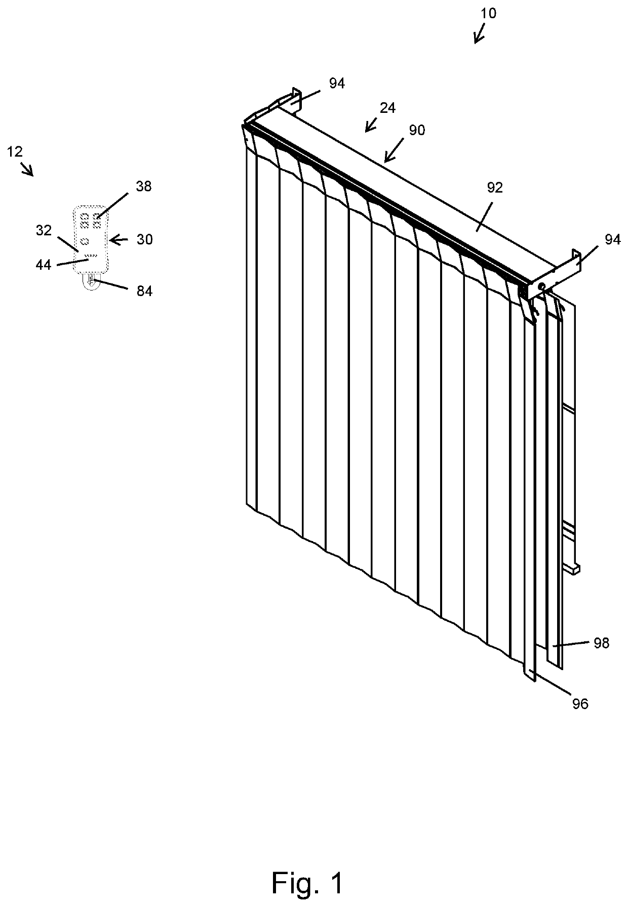
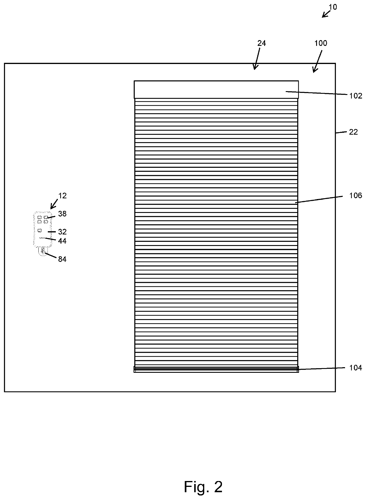
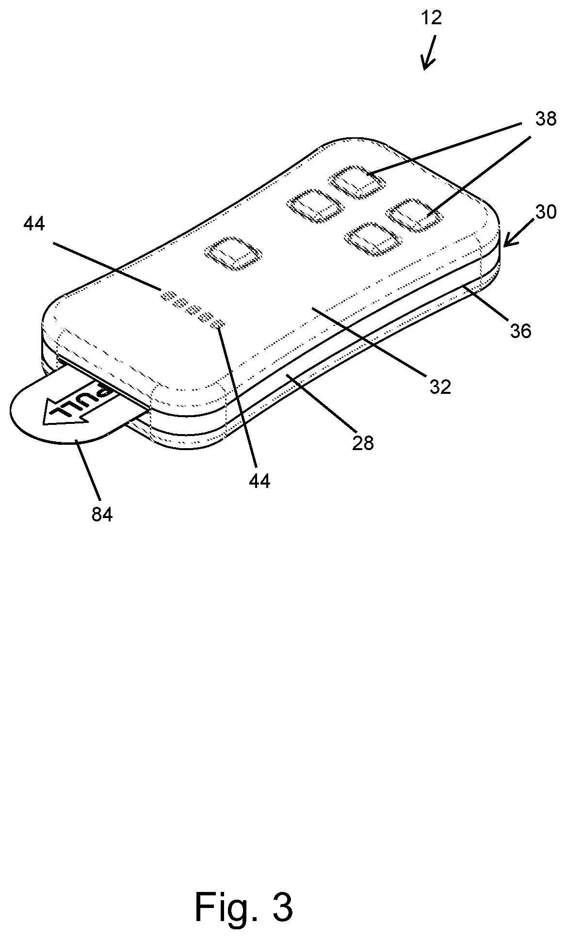

Image

  • Low profile remote and wall plate apparatus
  • Low profile remote and wall plate apparatus
  • Low profile remote and wall plate apparatus

Examples


Embodiment Construction

[0064]In the following detailed description, reference is made to the accompanying drawings which form a part hereof, and in which is shown by way of illustration specific embodiments in which the disclosure may be practiced. These embodiments are described in sufficient detail to enable those skilled in the art to practice the disclosure, and it is to be understood that other embodiments may be utilized and that mechanical, procedural, and other changes may be made without departing from the spirit and scope of the disclosure(s). The following detailed description is, therefore, not to be taken in a limiting sense, and the scope is defined only by the appended claims, along with the full scope of equivalents to which such claims are entitled.

[0065]As used herein, the terminology such as vertical, horizontal, top, bottom, front, back, end and sides are referenced according to the views presented. It should be understood, however, that the terms are used only for purposes of descript...


PUM


Abstract

A multi-function remote control system and mounting apparatus is presented. The remote control configured to magnetically attach and detach from an adhering plate or mounting plate located against a wall or other surface. The remote control is configured to self-center or self-orient in flush, planar engagement with an adhering plate or mounting plate. The remote control includes a plurality of push buttons wherein when pressed a plurality of window coverings are moved to a predetermined position. The mounting features of the remote control can be completely concealed from view for an aesthetically pleasing appearance. The adhering plate includes an adhesive which adheres the adhering plate to the wall for easy and convenient installation.

Description

CROSS REFERENCE TO RELATED APPLICATIONS[0001]This application claims priority to U.S. Provisional Application No. 62 / 793,955 which was filed on Jan. 18, 2019, the entirety of which is incorporated herein fully by reference.FIELD OF THE DISCLOSURE[0002]This disclosure relates to control technology, such as remote controls. More specifically, and without limitation, this disclosure relates to a low profile remote control system. More specifically, and without limitation, this disclosure relates to a low profile remote control system and a means for attaching the remote control to a surface such as a wall.BACKGROUND OF DISCLOSURE[0003]Remote controls are old and well known in the art. Conventional remote controls have been utilized to remotely control countless electronic devices such as garage doors, television sets and door locks on vehicles, to name a few. While the capability, range, durability and functionality of remote controls have improved over time, substantial deficiencies s...

Claims


Application Information

Patent Timeline
Patent Type & Authority Patents(United States)
IPC IPC(8): F16M11/00F16M13/02F16B1/00
CPCF16M13/02F16B1/00F16B2001/0035F16M11/041F16M13/00F16B2200/83
Inventor MULLET, WILLIS J.HAND, SCOTTPOULTON, MIKE
Owner CURRENT PROD CORP
Learn More