Wavelength converting element, light source device, and display device

a technology of light source device and converting element, which is applied in the direction of instruments, lighting and heating apparatus, semiconductor lasers, etc., can solve the problems of reducing the degree of freedom in terms of wavelength selection and radiation angle control

Active Publication Date: 2022-02-15
SEIKO EPSON CORP
View PDF8 Cites 0 Cited by
  • Summary
  • Abstract
  • Description
  • Claims
  • Application Information

AI Technical Summary

Problems solved by technology

This poses a problem in that these receive a constraint from each other, which results in a reduction in the degree of freedom in terms of wavelength selection and control of radiation angle.

Method used


Image

  • Wavelength converting element, light source device, and display device
  • Wavelength converting element, light source device, and display device
  • Wavelength converting element, light source device, and display device

Examples


first embodiment

[0037]Below, a first exemplary embodiment according to the present disclosure will be described with reference to FIGS. 1 to 3.

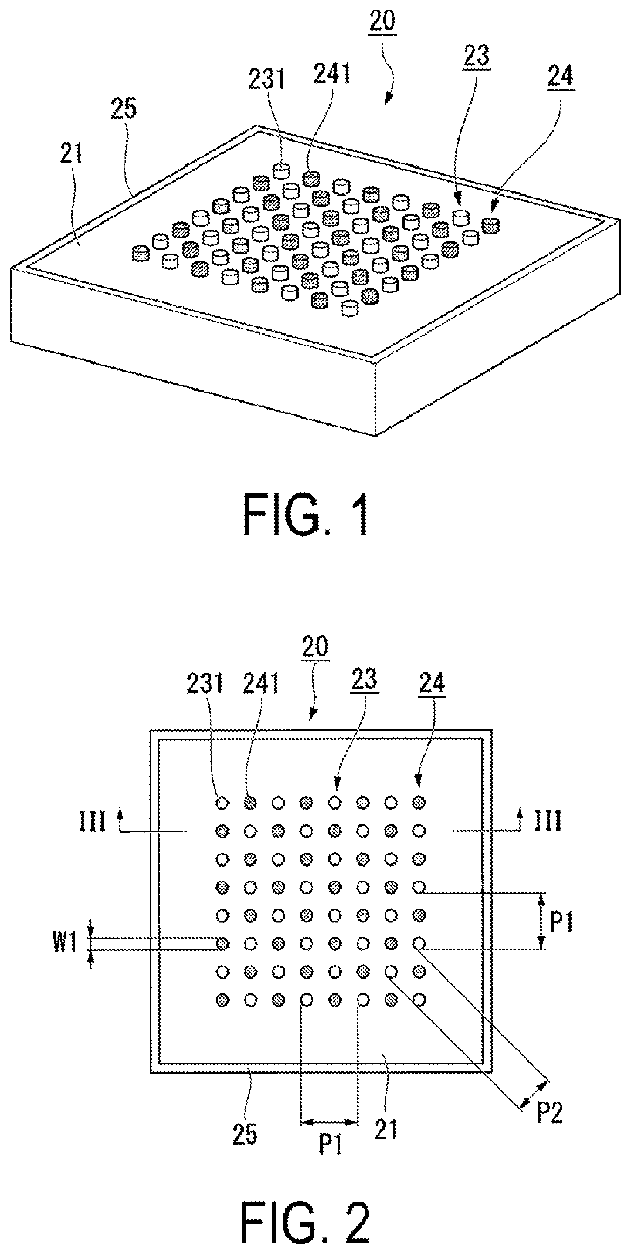
[0038]FIG. 1 is a perspective view of a wavelength converting element 20 according to the first exemplary embodiment. FIG. 2 is a plan view of the wavelength converting element 20. FIG. 3 is a cross-sectional view of the wavelength converting element 20 taken along the line III-III in FIG. 2. Note that, in the drawings, the dimensions of some components may be scaled differently for ease of understanding for the components.

[0039]As illustrated in FIGS. 1 to 3, the wavelength converting element 20 according to the present exemplary embodiment includes a wavelength converting body 21, a first dielectric layer 22, a metallic antenna array 23 (metallic antenna group), a dielectric antenna array 24 (dielectric antenna group), and a light reflection layer 25. Note that the light reflection layer 25 may be a light-absorbing layer, as described below.

[0040]In this d...

second embodiment

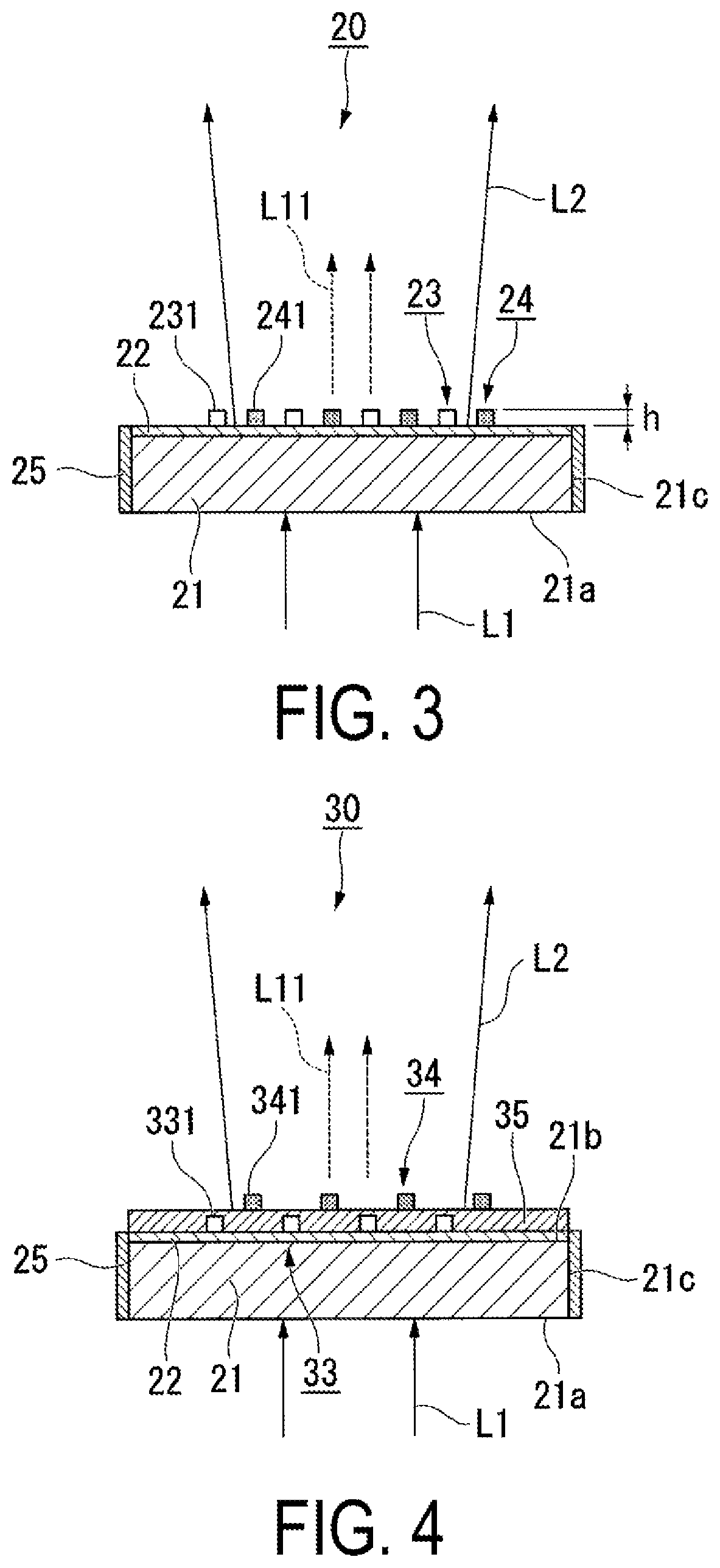
[0067]Below, a second exemplary embodiment according to the present disclosure will be described with reference to FIG. 4.

[0068]While a wavelength converting element according to the second exemplary embodiment has a basic configuration similar to that of the first exemplary embodiment, the arrangement of an antenna array differs from that of the first exemplary embodiment. Thus, the entire explanation of the wavelength converting element will not be repeated.

[0069]FIG. 4 is a cross-sectional view of a wavelength converting element 30 according to the second exemplary embodiment.

[0070]In FIG. 4, the same reference characters are attached to constituent elements common to those in the drawings used in the first exemplary embodiment, and explanation thereof will not be repeated.

[0071]As illustrated in FIG. 4, the wavelength converting element 30 according to the present exemplary embodiment includes the wavelength converting body 21, the first dielectric layer 22, a metallic antenna a...

first modified example

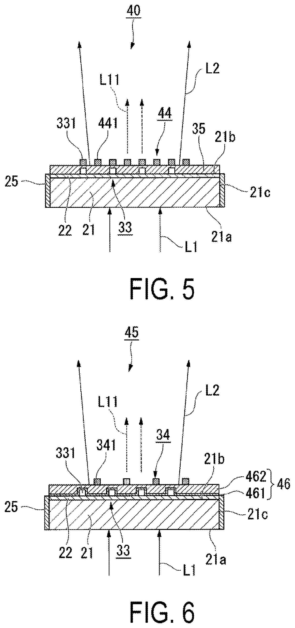
[0080]FIG. 5 is a cross-sectional view of a wavelength converting element 40 according to a first modification example.

[0081]In the wavelength converting element 40 according to the first modification example, some dielectric antennas 441 of a plurality of dielectric antennas 441 that constitute a dielectric antenna array 44 are disposed immediately above the metallic antenna 331, as illustrated in FIG. 5. In other words, some dielectric antennas 441 are disposed at positions overlapping with the metallic antenna 331 in plan view. This makes it possible to freely set the pitch of the dielectric antenna array 44 in a manner such that it is narrower than the pitch of the metallic antenna array 33.


PUM

PropertyMeasurementUnit
wavelength bandaaaaaaaaaa
thicknessaaaaaaaaaa

Abstract

A wavelength converting element according to the present disclosure includes: a wavelength converting body including an incident surface and an exit surface and configured to perform wavelength conversion on a primary light in a first wavelength band, entered from the incident surface, thereby generating a secondary light in a second wavelength band, which differs from the first wavelength band, the wavelength converting body emitting the secondary light from the exit surface; a metallic antenna group provided in a close vicinity of the wavelength converting body and including a plurality of metallic antennas disposed so as to be spaced apart from each other at a distance of substantially an optical wavelength of the secondary light in the wavelength converting body; and a dielectric antenna group including a plurality of dielectric antennas and provided so as to face the exit surface of the wavelength converting body.

Description

[0001]The present application is based on, and claims priority from JP Application Serial Number 2019-139950, filed on Jul. 30, 2019, the disclosure of which is hereby incorporated by reference herein in its entirety.BACKGROUND1. Technical Field[0002]The present disclosure relates to a wavelength converting element, a light source device, and a display device.2. Related Art[0003]A wavelength converting element is an optical element that converts inputted excitation light into light having a wavelength band different from that of the excitation light, and is used as a light source of a display device such as a projector. JP-A-2018-13688 described below discloses a wavelength converting device that includes a wavelength converting body including a phosphor plate, and also includes an antenna array including a plurality of metallic antennas formed on the wavelength converting body.[0004]JP-A-2018-13688 describes that, when the metallic antenna is irradiated with light, the field streng...

Claims


Application Information

Patent Timeline
Patent Type & Authority Patents(United States)
IPC IPC(8): G02B5/00F21V9/30H01L31/055H01L33/50H01L31/054H01S5/06H01S5/00
CPCG02B5/008F21V9/30H01L31/055H01L31/0549H01L33/508H01S5/0087H01S5/0609G03B21/204Y02E10/52
Inventor MATSUKI, HAYATO
Owner SEIKO EPSON CORP
Why Eureka
Try Eureka