Vehicle safety
a technology for vehicles and vehicles, applied in the field of vehicles, can solve the problems of unavoidable serious injuries, and achieve the effect of better protection for drivers
- Summary
- Abstract
- Description
- Claims
- Application Information
AI Technical Summary
Benefits of technology
Problems solved by technology
Method used
Image
Examples
first embodiment
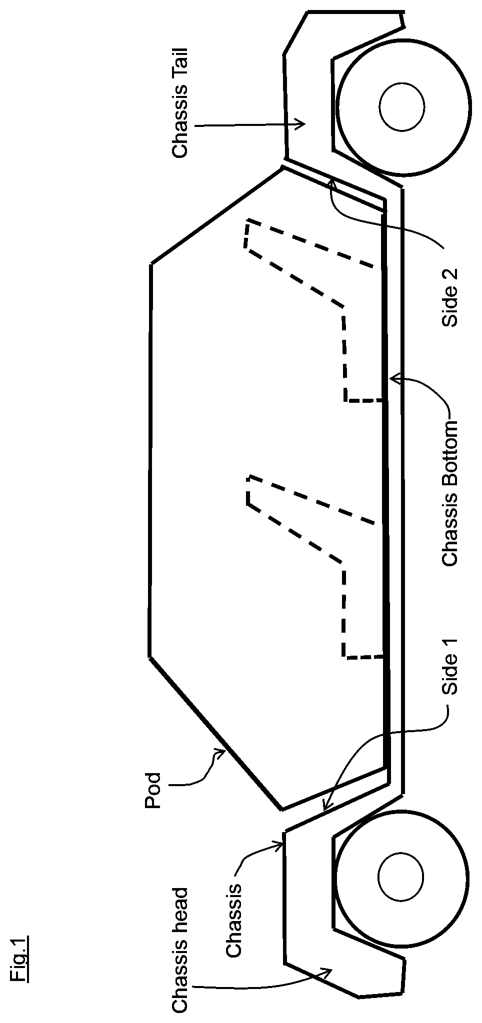
[0023]According to the present invention and referring to FIG. 1, in an exemplified vehicle, a pod is detachably secured to a chassis by an attachment and detachment device which may be a multi-point electro-mechanical locking system, and when a safety system detects or anticipates a collision, it will issue a signal, to firstly cause the attachment and detachment device to detach the pod from the chassis, as well as a collision detection signal, as will be discussed herein below in details.
[0024]The safety system can use any of a variety of technologies including but not limited to a shock / impact sensor, camera, a LiDAR system, infra-red sensor system, radar system (including but not limited to millimeter wave radar, noise radar, micro-power impulse radar, and ultra wideband radar), acoustical system, artificial intelligence system or a combination of these, and may include a crash anticipatory unit such as the one as disclosed in U.S. Pat. No. 8,041,483.
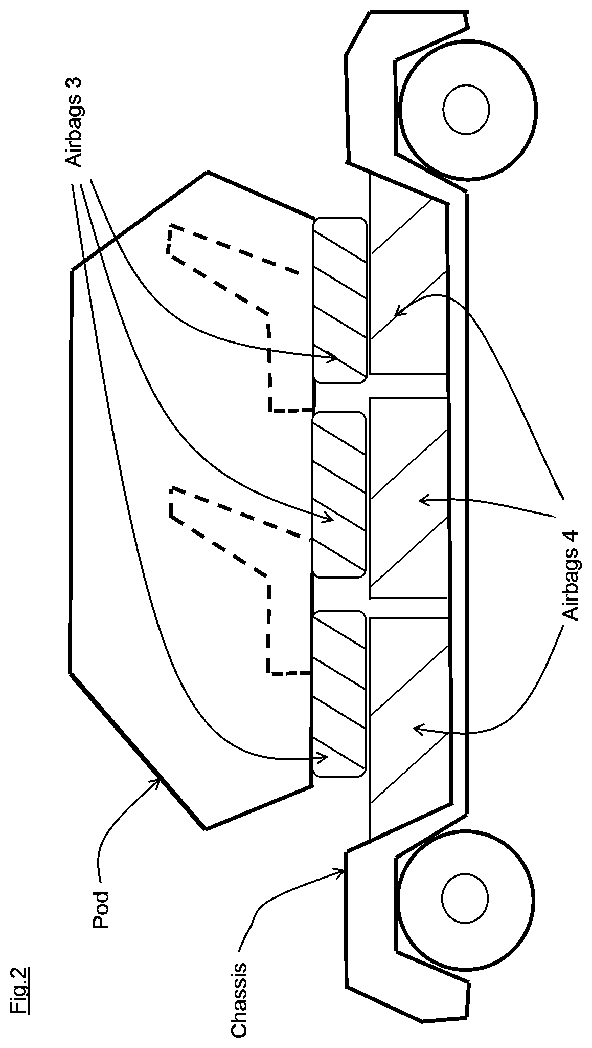
[0025]As shown in FIG. 1, t...
second embodiment
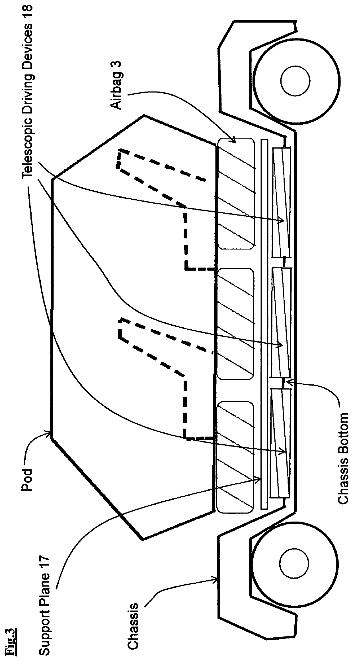
[0035] and referring to FIG. 3, a vertically movable support plane 17 is provided, and it lays flat on the chassis bottom, when no accident, to allow the pod resting on it be detachably secured to the chassis. The first collision detection signal will cause mechanical or hydraulic or pressurized fluid device(s) (not shown in FIG. 3), or the like, to extend the telescopic driving devices 18, thereby moving the support plane 17 upward, for facilitating the above-mentioned movement of the pod towards the non-flush part.
[0036]In the first and second embodiments, airbags 4 and / or support plane 17 and / or telescopic driving devices 18 may itself / themselves, or with additional reinforcing material and / or structure, be capable of acting as an impact resisting and / or absorbing device to minimize / prevent intrusion by an external object into the vehicle. And, if a side impact on the vehicle is detected / anticipated by the safety system, it will issue a collision detection signal, says, third col...
third embodiment
[0043] and referring to FIG. 4, for simplicity and by way of example, the exemplified vehicle has no airbags 3, 4, support plane 17, or telescopic driving devices 18. The pod is connected with the chassis with chains (alternatively, steel cable or the like) 5, 6, 7, 8, and they are for moving the pod, when the pod is detached from the chassis in the above-mentioned manner.
[0044]Each chain has one end respectively attached to a different corner, says, corner A, or to a position close to corner A, of the pod, and the other end of each chain is respectively attached to a different anchor installed on the chassis, and the anchor is close to a corner of the pod, which is adjacent to corner A. And, each chain will cause the pod to move in a direction towards the anchor it attached, if retracted.
[0045]When the safety system detects / anticipates a side impact, on side 15 or 16, it will issue respectively corresponding signals to cause an electro-mechanical device to retract both chains 5 and...
PUM
 Abstract
Description
Claims
Application Information
 - R&D
- Intellectual Property
- Life Sciences
- Materials
- Tech Scout
- Unparalleled Data Quality
- Higher Quality Content
- 60% Fewer Hallucinations
Browse by: Latest US Patents, China's latest patents, Technical Efficacy Thesaurus, Application Domain, Technology Topic, Popular Technical Reports.
© 2025 PatSnap. All rights reserved.Legal|Privacy policy|Modern Slavery Act Transparency Statement|Sitemap|About US| Contact US: help@patsnap.com


