Optical device

a technology of optical couplers and optical components, applied in the field of optical devices, can solve problems such as unbalanced optical couplers, and achieve the effect of minimising losses and maximising the effectiveness of feedback

Active Publication Date: 2022-02-22
REDWAVE LABS LTD
View PDF17 Cites 0 Cited by
  • Summary
  • Abstract
  • Description
  • Claims
  • Application Information

AI Technical Summary

Benefits of technology

[0009]The unbalanced optical coupler may be any optical element with the ability to directionally limit optical power. For example, the unbalanced optical coupler may comprise an optical isolator, or the like. The unbalanced optical coupler may be arranged to couple the seed signal into the laser source at a power level selected to promote preferential stimulated emission within a narrower linewidth. The power level may be selected in conjunction with information about losses associated with a lasing cavity of the laser source. This is to ensure that the seed signal is not lost in the cavity, and to ensure that it does not dominate the lasing process. Moreover, by limiting the power of the signal returned back to the lasing element, the laser emission may still be adjustable over a useful range, e.g. to permit fine tuning of the laser emission to coincide exactly with cavity resonances. Having smaller feedback signal allows wider fine tuning (by laser current or temperature) to get exactly to the required wavelength.
[0010]By controlling the power of seed signal such that only a small portion thereof influences the lasing cavity, the narrowing effect of the preferential stimulated emission can be enhanced. Different types of laser may require different amount of feedback for optimal operation. The control provided by an optical isolator placed between cavity and the laser source enables the feedback to be varied so that the device is operable with a variety of laser sources. The seed signal may have an optical power than is 20 dB or more less than the optical power of the source signal, preferably 30 dB less, i.e. 1000 times less. For example, the optical isolator may allow the seed signal optical power to vary from 0.1% to about 10% of the source signal optical power.
[0017]It may be particularly advantageous to fabricate as much of the device as possible from the same material as the substrate. This can enable errors caused by temperature changes to be compensated in a straightforward manner.
[0023]The optical path may comprise a first path portion extending between the first cavity mirror and the intermediate mirror, and a second path portion extending between the intermediate mirror and the second cavity mirror, wherein the first path portion is disposed at an acute angle relative to the second path portion. The optical path may thus have a V-shape. This may be advantageous for provided a compact structure.
[0024]The optical cavity may have a resonant optical frequency that is within an output bandwidth of the laser source, and preferably matched to the laser frequency itself. This may maximise the effectiveness of the feedback.

Problems solved by technology

The unbalanced optical coupler may be any optical element with the ability to directionally limit optical power.

Method used


Image

  • Optical device

Examples


Embodiment Construction

; FURTHER OPTIONS AND PREFERENCES

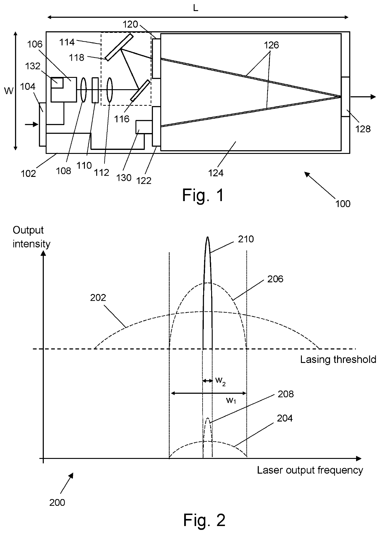
[0032]The present invention relates to an optical device configured to output a narrow linewidth laser beam using an all-optical technique. The optical device may be provided in a compact package, in which the linewidth narrowing optics are provided or integrated on the same substrate as a laser source, such as a diode laser. FIG. 1 is a schematic plan view of a narrow linewidth laser optical source 100 that is an embodiment of the invention. The optical source 100 comprises a substrate 102, e.g. made from fused silica. Components of the optical source 100 are either mounted or integrally formed on the substrate 102, as explained below.

[0033]A laser 106 is mounted on the substrate 102. The laser 106 may be a laser diode, such as a distributed feedback (DFB) laser diode, although other types of laser may be used, in which the gain of the laser is spectrally wider than the feedback (seed) signal. The laser 106 can be an off-the-shelf component that is ...


PUM

PropertyMeasurementUnit
wavelengthaaaaaaaaaa
sizeaaaaaaaaaa
reflectivityaaaaaaaaaa

Abstract

A narrow linewidth laser in which an all-optical feedback line-up is used to improve the linewidth from a conventional laser source, such as a laser diode. The feedback line-up comprises an optical device having a controllable unbalanced optical coupler arranged on a cavity input path to couple a source signal from the laser source into the optical cavity, and to couple a seed signal received back from the optical cavity into the laser source. The seed signal has a lower power than the source signal. The unbalanced optical coupler may be an optical isolator arranged to couple the seed signal into the laser source at a power level selected to promote preferential stimulated emission within a narrower linewidth. By controlling the power of seed signal such that only a small portion thereof influences the lasing cavity, the narrowing effect of the preferential stimulated emission can be enhanced.

Description

CROSS-REFERENCE TO RELATED APPLICATIONS[0001]The present application claims priority from Great Britain Patent Application No. 1709922.7 filed on Jun. 21, 2017, the entire contents of which are hereby incorporated by reference.FIELD OF THE INVENTION[0002]The invention relates an optical device for generating a narrow linewidth laser beam. In particular, the invention relates to an optical device in which an all-optical feedback technique is used to narrow the linewidth output from a laser diode.BACKGROUND TO THE INVENTION[0003]The use of laser light in modern technology is ubiquitous. Some uses require the light output from the laser to occupy a very limited optical spectrum, i.e. to have a very small frequency bandwidth (referred to herein as a linewidth). Such lasers are typically known as “narrow linewidth” lasers.[0004]Known types of semiconductor-based narrow linewidth lasers include distributed feedback (DFB) laser diodes and distributed Bragg (DBR) reflector lasers. These las...

Claims


Application Information

Patent Timeline
Patent Type & Authority Patents(United States)
IPC IPC(8): H01S5/065H01S3/30H01S5/00H01S3/067H01S3/1055H01S3/13H01S5/12H01S5/023H01S5/0233H01S5/0235H01S5/02326H01S3/10G02F1/09
CPCH01S3/302H01S3/0675H01S3/1055H01S3/1305H01S5/0064H01S5/0656G02F1/093H01S3/10084H01S3/10092H01S5/005H01S5/0071H01S5/0078H01S5/023H01S5/0233H01S5/0235H01S5/02326H01S5/12H01S2301/02
Inventor PERMOGOROV, DMITRI
Owner REDWAVE LABS LTD
Why Eureka
Try Eureka