
X-ray inspection apparatus

Active Publication Date: 2022-03-08
SHIMADZU CORP
View PDF6 Cites 0 Cited by
  • Summary
  • Abstract
  • Description
  • Claims
  • Application Information

AI Technical Summary

Benefits of technology

[0004]While the geometric magnification factor can be increased by shortening the distance from the X-ray source to the object, in r

Problems solved by technology

The extent of the region of the focal point exerts deleterious effect on an image which is called blurring, and the influence of this blurring on the image becomes larger as the geometric magnification factor increases.
While it is possible, by making the focal point size of the X-ray source small, to reduce blurring even in the case of photography at a high geometric magnification factor, there is a physical limit to making the focal point size small.
Also, making the focal point size small generally reduces the X-ray dose emitted from the X-ray source.
This leads to a problem such as an increase in image noise or an elongation in the photographing time.
However, increasing the distance between the X-ray source and the X-ray detector causes a problem that the apparatus becomes large.
Therefore, the problem such as an increase in image noise or an elongated ph

Method used


Image

  • X-ray inspection apparatus
  • X-ray inspection apparatus
  • X-ray inspection apparatus

Examples


first embodiment

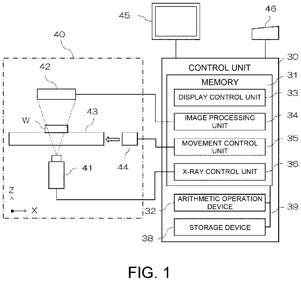
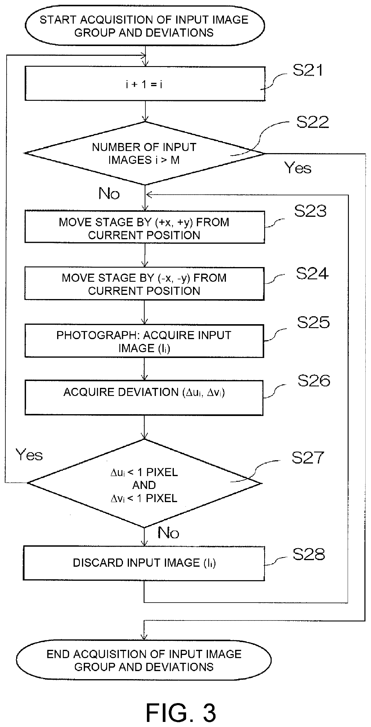
[0035]Details of the step of acquiring the input image group and the deviations in step S14 will be further described. FIG. 3 is a flowchart for describing a procedure for acquiring the input image group and the deviations according to a

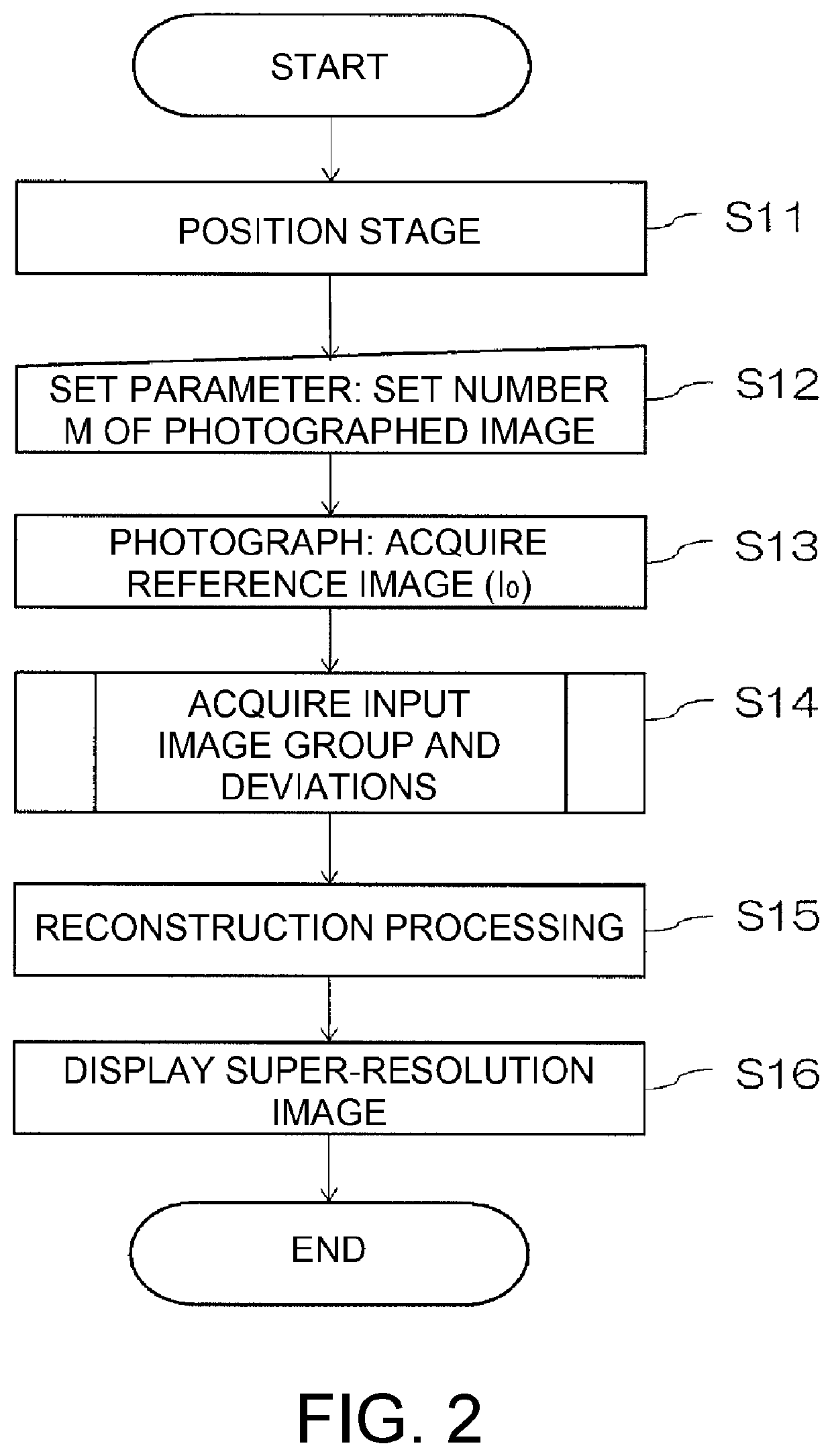
[0036]Step S14 corresponds to first and second steps of the above-described super-resolution reconstruction processing, and is a step of acquiring the input image group by executing continuous X-ray photography for the super-resolution reconstruction processing. When step S14 is started, the image processing unit 34 sequentially acquires the input image (Ii) and a deviation (Δui, Δvi) used for the reconstruction processing (step S15) described later with respect to a first image to an M-th image. Note that i is an integer equal to or larger than zero, and i=0 is the first input image that is the reference image (I0) acquired in step S13. In step S21, 1 is added to the current i (0+1=1 for the first time) to update i. The control unit 30 determines wh...

second embodiment

[0043]Another aspect of the step of acquiring the input image group and the deviations will be described. FIG. 4 is a flowchart for describing a procedure for acquiring an input image group and deviations according to a FIGS. 5 and 6 are schematic diagrams for describing a step of cutting out the images acquired as the input image group.

[0044]In the present embodiment, an image (I′0) is created from the reference image (I0) acquired in step S13. The image (I′0) is a second reference image cut out from the reference image (I0), and in the present embodiment, an input image (I′i) of the same size as the image (I′0) and a deviation (Δu′i, Δv′i) are acquired as the input image group and the positional deviation for super-resolution reconstruction processing.

[0045]As shown in FIG. 5, the control unit 30 causes the image processing unit 34 to create the image (I′0) from the reference image (I0) by cutting out a rectangular image having a distance w in the X direction and a distance h in ...


PUM


Abstract

Utilizing random variation (repeated positioning error) when reciprocating operation is repeatedly performed in which a stage is moved by (+x, +y) pulses toward an arbitrary position perpendicular to an optical axis of X-rays extending from an X-ray source to an X-ray detector, and then, is moved from there by (−x, −y) pulses, an image group of images obtained by moving in parallel to each other is acquired, and an image processing unit finds a deviation between the images, and acquires an input image group in which each of the images has the deviation at a subpixel level. The image processing unit executes a reconstruction processing, using the input image group in which each of the images has the deviation at the subpixel level to generate a super-resolution image.

Description

CROSS-REFERENCE TO RELATED APPLICATION[0001]This application is a 371 application of the International PCT application serial no. PCT / JP2018 / 019543, filed on May 21, 2018. The entirety of the above-mentioned patent application is hereby incorporated by reference herein and made a part of this specification.BACKGROUNDTechnical Field[0002]The present invention relates to an X-ray inspection apparatus that performs X-ray photography for super-resolution reconstruction processing.Background Art[0003]As an apparatus configured to observe an internal structure of an industrial product or the like under non-destructive conditions, conventionally, there have been known an industrial fluoroscopic apparatus for obtaining a fluoroscopic image by irradiating an object with X-rays, and an industrial X-ray CT apparatus for obtaining a tomographic image of an object (see Patent Literature 1 JP 2006-317249 A). An X-ray detector has a light receiving region of a preset size and a preset number of pi...

Claims


Application Information

Patent Timeline
IPC IPC(8): G01N23/00G01N23/046
CPCG01N23/046G01N2223/3307G01N2223/401G06T3/4069G01N2223/417
Inventor IWAO, YOSHIHIKO
Owner SHIMADZU CORP
Learn More