Valve

a valve body and valve body technology, applied in the field of valves, can solve problems such as abnormal noise, and achieve the effect of preventing vibration of the valve body

Active Publication Date: 2022-03-15
ADVICS CO LTD
View PDF9 Cites 1 Cited by
  • Summary
  • Abstract
  • Description
  • Claims
  • Application Information

AI Technical Summary

Benefits of technology

[0006]According to the present disclosure, when the valve is opened, the valve body is guided by the guiding part in the predetermined one direction, and the valve body is prevented from moving in other directions. As the movement of the valve body is restricted to one direction, the position of the flow path formed between the valve body and the valve seat becomes a constant position. Thus, the valve body may be prevented from swinging in various directions, and the vibration of the valve body may be prevented. Furthermore, when the valve body moves, the valve body relatively moves with respect to the guiding part, so that the valve body and the pressing member may be prevented from moving integrally.

Problems solved by technology

When opening and closing the valve, the valve body vibrates due to the negative pressure generated when the fluid passes through the gap between the valve body and the valve seat, which causes abnormal noise.

Method used


Image

  • Valve
  • Valve
  • Valve

Examples


Embodiment Construction

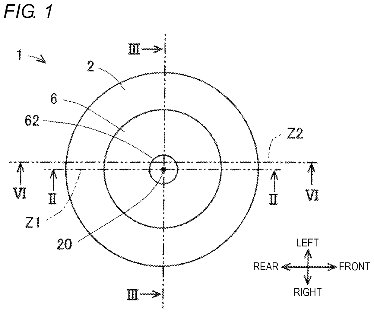
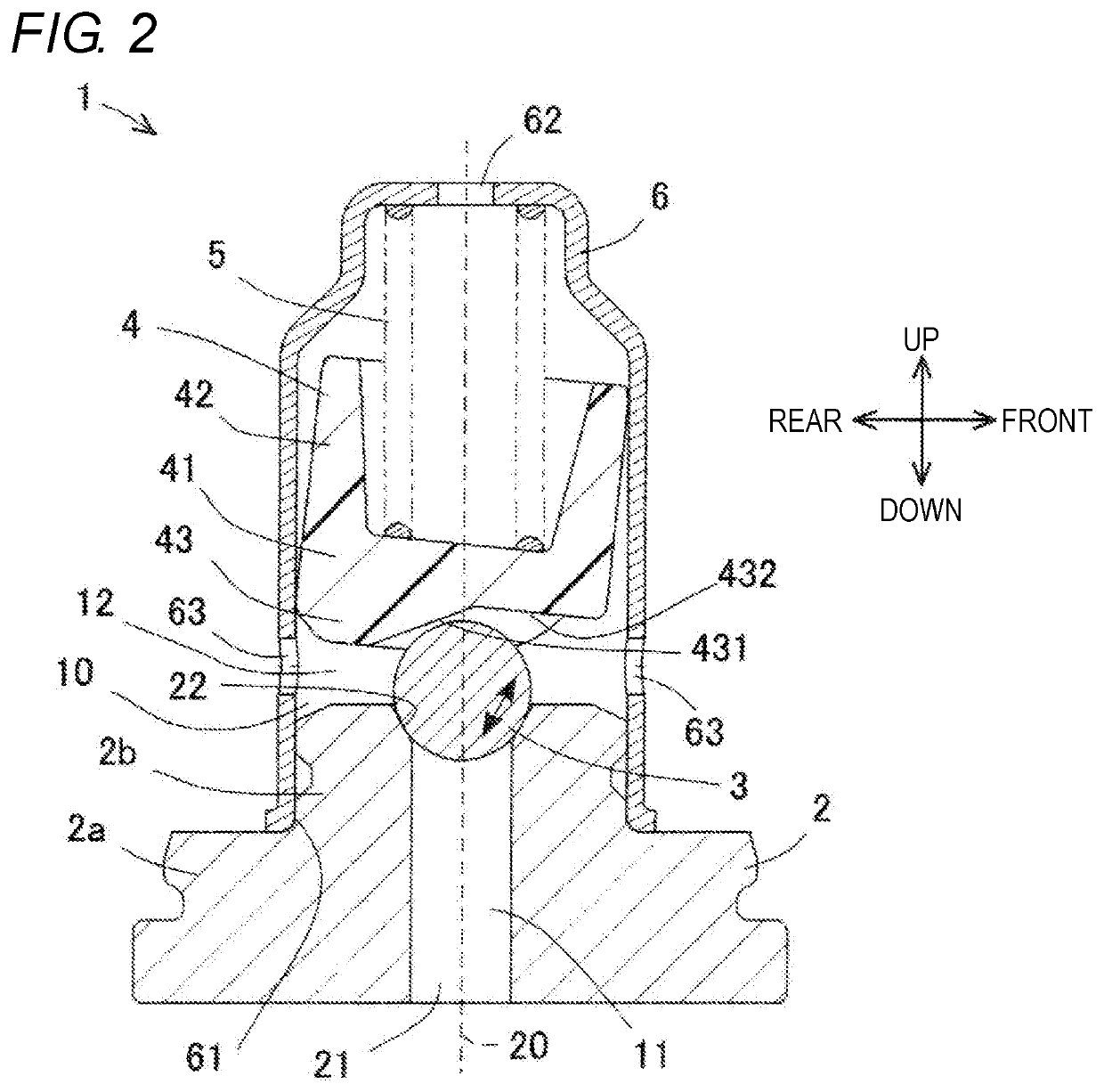
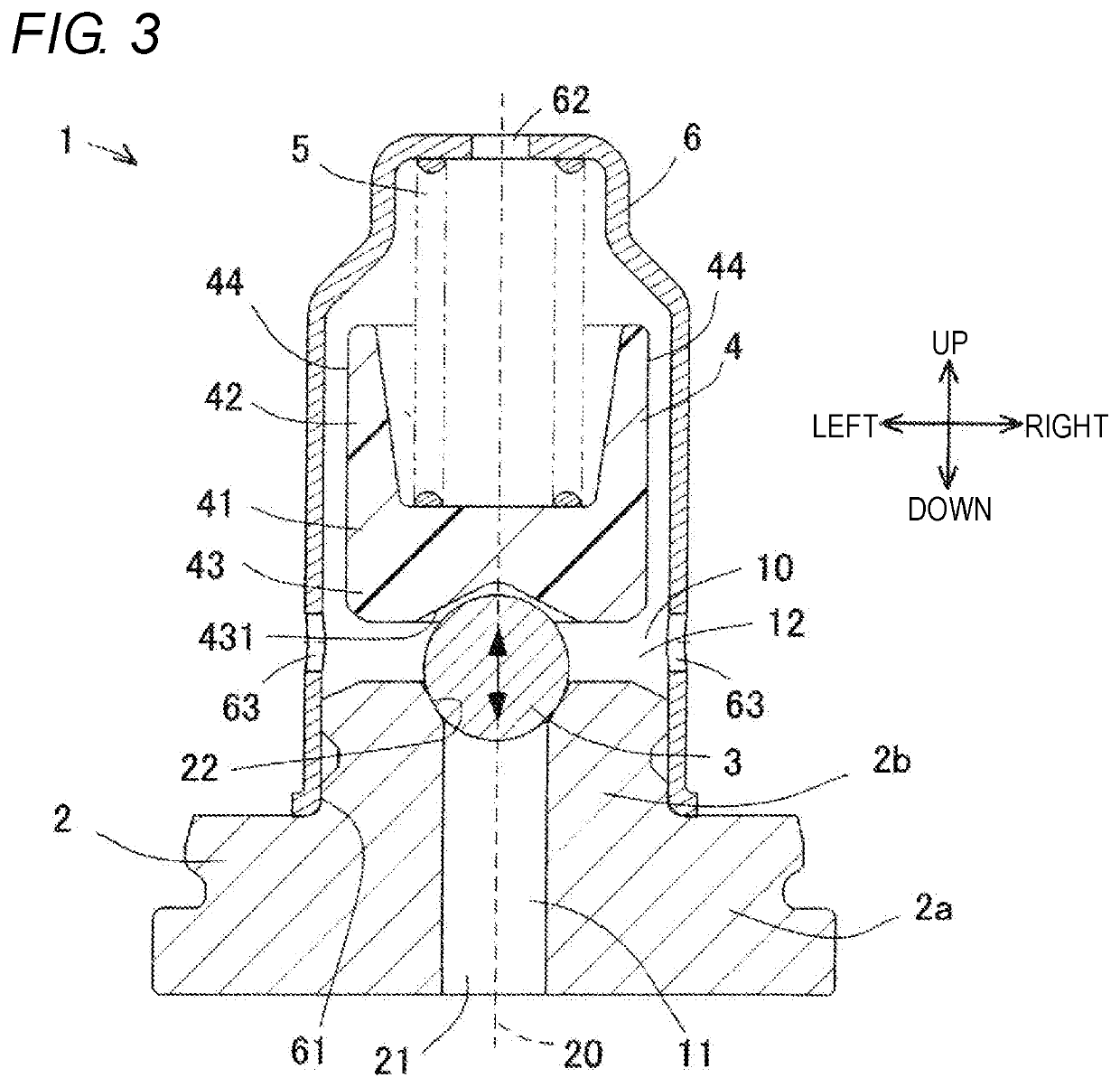
[0016]Hereinafter, an embodiment of the present disclosure will be described based on the drawings. The drawings are schematic diagrams, and in particular, FIGS. 1, 5, 6, 8, and 9 are conceptual diagrams in which the shapes are simplified. The valve 1 of the present embodiment is a valve having a function of a relief valve (i.e., relief valve). As illustrated in FIGS. 1 to 3, the valve 1 includes a valve seat 2 in which a valve hole 21 is formed, a spherical valve body 3, a pressing member 4, an urging member 5, and a retainer 6. Hereinafter, unless particularly stated, the “axial direction” is the direction in which the valve hole 21 extends, and the “radial direction” is the radial direction of the valve hole 21. In other words, in the present embodiment, the axial direction is the axial direction of the valve seat 2, and the radial direction is the radial direction of the valve seat 2. Hereinafter, for the sake of explanation, the right side, left side, upper side, and lower side...


PUM


Abstract

A valve of the present disclosure includes a valve seat formed with a valve hole; a spherical valve body; and a pressing member that presses the valve body toward the valve hole, the valve hole being closed by the valve body pressed by the pressing member; where the pressing member includes a guiding part that, when a force opposing the urging force acts on the valve body by greater than or equal to a prescribed value, separates the valve body away from the valve seat while guiding and relatively moving the valve body in a predetermined one direction.

Description

TECHNICAL FIELD[0001]The present disclosure relates to a valve.BACKGROUND ART[0002]An example of the valve is a relief valve including a plunger, a valve body, a valve seat, and a spring. The relief valve is configured such that the spring presses the plunger and the valve body toward the valve seat, and the valve body closes the valve hole provided in the valve seat. When a pressure greater than or equal to a predetermined pressure is applied to the valve body through the valve hole, the valve body presses the plunger against the urging force, and the valve body moves thus opening the valve hole. When opening and closing the valve, the valve body vibrates due to the negative pressure generated when the fluid passes through the gap between the valve body and the valve seat, which causes abnormal noise. Here, Japanese Unexamined Patent Application Publication No. 2012-82762 discloses a relief valve configured such that a ball, or valve body, is pressed against a wide-width portion on...

Claims


Application Information

Patent Timeline
Patent Type & Authority Patents(United States)
IPC IPC(8): F16K15/04
CPCF16K15/044F16K17/0406F16K17/0433F16K2200/305
Inventor TANIZAKI, KAZUKI
Owner ADVICS CO LTD
Why Eureka
Try Eureka