Centrifugal pump

a centrifugal pump and centrifugal technology, applied in the direction of engine components, non-positive displacement fluid engines, liquid fuel engine components, etc., can solve the problems of reducing efficiency, prone to wear, and complicated sealing arrangement with regard to design, so as to achieve low frictional losses.

Active Publication Date: 2022-03-22
GRUNDFOS HLDG
View PDF11 Cites 0 Cited by
  • Summary
  • Abstract
  • Description
  • Claims
  • Application Information

AI Technical Summary

Benefits of technology

[0006]Against this background, it is an object of the invention according to the application, to design a centrifugal pump of the known type, such that on the one hand an as good as possible sealing arises between the suction port and the stationary pump part during operation of the pump, and on the other hand as low as possible frictional losses arise.
[0008]The basic concept of this solution according to the invention, is to let the sealing run in the manner of a plain bearing, so that a fluid film is built up between the sealing ring and the surface, on which this bears, at least on delivery operation of the pump, which is to say when the impeller rotates with respect to the stationary pump part, and hence viscous friction and not a full mechanical friction arises between the sealing ring and the counter sealing surface. Such a viscous friction minimizes the friction losses within the seal, but on the other hand permits the leakage losses within the sealing arrangement to be keep extremely low. Not only is the friction within the sealing arrangement significantly reduced due to the viscous friction, but the wearing of the seal itself is also reduced to a minimum.
[0013]The basic concept of this solution is to design the sealing ring with a different stiffness over its periphery and to arrange it such that the hydraulic forces due to the pressure difference between the delivery side and the suction side press the sealing ring towards the counter sealing surface to a different great extent over its periphery, on operation of the pump, thus on rotation of the impeller with respect to the stationary pump part. Thereby, according to the invention, one preferably envisages the sealing ring being configured and arranged such that it is arranged distanced to the counter sealing surface, in particular to the suction port, in the idle condition of the pump, thus when the impeller is at a standstill. Such an arrangement, with which the sealing ring does not bear on the counter sealing surface until there is a differential pressure between the suction side and the delivery side of the impeller, and on account of its structure is configured such that sections are present which bear on the counter sealing surface and alternatingly sections which do not bear on this or only with a reduced force, can likewise realize the principle according to the invention, with which the seal on operation is lubricated due to the fluid film, in the manner of a plain bearing. The latter arrangement moreover has the advantage that the sealing, i.e. the bearing of the sealing ring sections on the counter sealing surface is only effected during operation and otherwise a significant distance exists between the sealing ring and the counter sealing surface, by which means on the one hand a certain self-cleaning effect occurs, and on the other hand for example a scaling of the sealing surface is counteracted, due to these being in movement. Moreover, a significant advantage results due to the fact that the tolerances in the region of the sealing arrangement are such that the manufacture and assembly are simplified, and thus the manufacturing costs reduced.
[0016]Not only can the targeted material weakening be effected by recesses on the outer periphery of the sealing ring, but also and / or by recesses on the inner periphery. The arrangement of the sealing ring with respect to the suction port must be taken into account with the arrangement of the recesses. The sealing ring is typically configured such that it bears on the outer periphery of the suction port, and then the sealing ring can be freely configured at its outer periphery, whereas recesses on the inner periphery are to be dimensioned such that no unallowably high leakage losses occur. Thereby, in particular, the recesses on the inner periphery can be configured such that they run out towards the suction side, so that a narrow peripheral ring forms there, and this ring prevents leakage.
[0017]It is particularly when the sealing ring sealing bears with its outer periphery on the suction port, that it can be advantageous to provide the recesses on the inner periphery of the sealing ring, wherein these are usefully arranged parallel to one another, for example in a manner parallel to the axis or obliquely to this.
[0018]According to an advantageous further development of the invention, the recesses are configured in a wedge-like manner seen in the peripheral direction. Such a design, in particular at the side of the sealing ring which is envisaged for contact on the counter sealing surface, has the advantage that a fluid film is reliably built up due to the wedge-like recesses which lie in the rotation direction and which are filled with delivery fluid on operation, and this film ensures a low-friction sliding of the sealing ring on the counter sealing surface.

Problems solved by technology

Although an almost complete sealing between the delivery side and the pressure side of the pump can be achieved by way of this, by which means leakage losses and thus efficiency losses due to leakage can be reduced, the friction between the sealing lip and the impeller however increases with the increasing pressure, which leads to friction losses reducing the efficiency as well as to a wearing on the sealing lip.
Although the frictional losses and thus also the wear can be reduced by way of this arrangement, the sealing arrangement however is complicated with regards to its design and is prone to wear due to the fact that a section of the sealing ring constantly bears on the sliding surface of the impeller.
The sealing of the suction port with respect to the stationary pump part by way of a sealing arrangement, although reducing the leakage losses, however increases the frictional losses within the pump, to the extent that the demands of a high sealing efficiency on the one hand and of low friction losses on the other hand are at odds with one another.
Only the reduction of the gap between the suction port and the stationary pump part in a manner free of sealing means is more favorable inasmuch as this is concerned, but this however increases the manufacturing tolerance and therefore the manufacturing costs.

Method used


Image

  • Centrifugal pump
  • Centrifugal pump
  • Centrifugal pump

Examples


Embodiment Construction

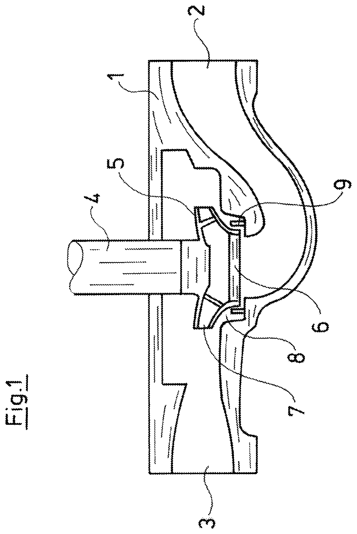
[0037]Referring to the drawings, the centrifugal pump which is represented in a greatly simplified manner in FIG. 1, comprises a stationary pump casing 1 which comprises a suction connection 2 as well as a delivery connection 3, in which a shaft 4 is rotatably mounted, said shaft driving an impeller 5 which is seated therein and whose axial suction port 6 is conductively connected to the suction connection 2 and whose downstream side 7 is arranged in a radial manner and conductively connected to the delivery connection 3.

[0038]The pump casing 1 here represents any stationary pump component, for example with a multi-stage pump represents the stationary part of a pump stage, which is to say that the principle representation represented by way of FIG. 1 can be applied to one or several arbitrary impellers with the respective stationary pump parts.

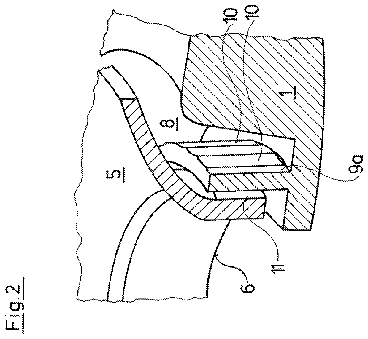
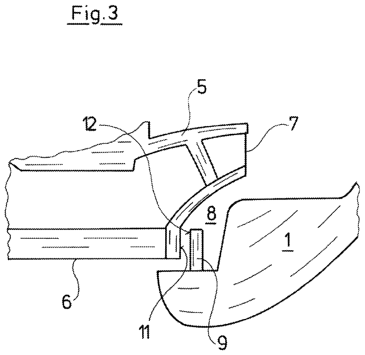
[0039]A leakage channel 8 which can be shut off by a sealing ring 9 in the pump, is formed between the downstream side 7 thus the delivery si...


PUM


Abstract

A centrifugal pump includes at least one pump stage, with a rotatable impeller (5) with a suction port (6) which is sealed with respect to a stationary pump part (1) by way of a sealing arrangement. The sealing arrangement includes a sealing ring (9) between the impeller (5) and the stationary pump part (1). The sealing arrangement is configured such that at least on delivery operation of the pump, the sealing arrangement has sealing sections which are distanced to the counter sealing surface and sealing sections which bear on the counter sealing surface, in an alternatingly successive manner considered in the peripheral direction of the sealing ring (9).

Description

CROSS REFERENCE TO RELATED APPLICATIONS[0001]This application is a United States National Phase Application of International Application PCT / EP2017 / 083121 filed Dec. 15, 2017, and claims the benefit of priority under 35 U.S.C. § 119 of European Application 16205241.9, filed Dec. 20, 2016, the entire contents of which are incorporated herein by reference.TECHNICAL FIELD[0002]The invention relates to a centrifugal pump with at least one pump stage, with a rotatable impeller with a suction port which is sealed with respect to a stationary pump part by way of a sealing arrangement, wherein the sealing arrangement comprises a sealing ring between the impeller and the stationary pump part.TECHNICAL BACKGROUND[0003]Such sealing arrangements are counted as belonging to the state of the art. A centrifugal pump, with which a sealing ring on the housing side is arranged in the region of the suction port of the pump and comprises a sealing lip which bears on the outer side of the impeller, in t...

Claims


Application Information

Patent Timeline
Patent Type & Authority Patents(United States)
IPC IPC(8): F04D29/16F04D17/08
CPCF04D29/161F04D17/08F05B2240/57F04D29/167F04D29/16
Inventor LUNDSTED POULSEN, BRIANSØGAARD LEDET, LASSE
Owner GRUNDFOS HLDG
Why Eureka
Try Eureka