Magnetically-inductive flow-measuring device, magnetic circuit device and method for the production of a magnetic circuit device

a magnetic circuit device and flow measurement technology, applied in the direction of measurement devices, volume/mass flow by electromagnetic flowmeters, instruments, etc., can solve the problems of high design cost and assembly cost of magnetic circuit devices of magnetically-inductive flow measurement devices

Active Publication Date: 2022-03-22
KRONE GMBH
View PDF14 Cites 0 Cited by
  • Summary
  • Abstract
  • Description
  • Claims
  • Application Information

AI Technical Summary

Benefits of technology

[0005]The object of the invention is to provide a magnetically-inductive flow-measuring device with a magnetic circuit device and a magnetic circuit device for a magnetically-inductive flow-measuring device, which can be carried out in an especially simple way and, moreover, economically.
[0008]The configuration according to the invention has the advantage that an economical magnetic circuit device can be produced in an especially simple way since only sheet elements have to be prepared and bent—and optionally connected to one another. Moreover, the magnetic circuit device saves space and thus makes it possible to produce a compact magnetically-inductive flow-measuring device.
[0011]In an alternative embodiment of the magnetically-inductive flow-measuring device according to the invention, the magnetic circuit device is made from multiple sheet elements, namely from a first sheet element, a second sheet element and a third sheet element. A part of the elements of the magnetic circuit device is produced by each sheet element. This configuration has the advantage that the mounting of the magnetic circuit device in the magnetically-inductive flow-measuring device is facilitated. In particular, the design of the magnetic circuit device around the coil is facilitated. Since the coil core also is formed by a part of the magnetic circuit device itself, the sheet elements have to be guided at least partially by the coil or by the interior of the coil. This can be carried out in an especially preferred way by the subsequent preferred further development:
[0019]Overall, the magnetically-inductive flow-measuring device according to the invention further has the advantage that for producing the magnetic circuit device, few—preferably one, two or three—sheet elements are required. This ensures that only a few connecting points or none at all are necessary between the sheet elements. Connecting points form a weak point of a magnetic circuit device, since the magnetic field can be disturbed in particular at the connecting points. According to the invention, a magnetic circuit device is provided, or a magnetically-inductive flow-measuring device is provided, which has few discontinuities for the magnetic field. In a preferred configuration, in which the magnetic circuit device is made from multiple sheet elements, the sheet elements are connected flush with one another and thus do not overlap. In an alternative configuration, the sheet elements are connected to one another in an overlapping manner. It is also conceivable that in the case of multiple sheet elements, a part of the sheet elements are connected to one another in an overlapping manner, and the other part of the sheet elements is connected flush with one another. The sheet elements are connected by, for example, welding, clinching or screwing or another known method.
[0021]It has been stated above that in the preferred configurations of the coil cores, the magnetic circuit device is designed in two parts, namely by a first coil core section and a second coil core section. In the case of the two-part production of the coil core, in a preferred configuration of the magnetically-inductive flow-measuring device according to the invention, the first coil core section and the second coil core section are arranged with one another in such a way that a gap is produced between the two coil core sections. The lines for the electrodes of the magnetically-inductive flow-measuring device are further preferably guided through these gaps. According to the invention, a secure and, moreover, space-saving guiding of the lines is thus ensured.

Problems solved by technology

Magnetically-inductive flow-measuring devices and in particular the magnetic circuit devices of magnetically-inductive flow-measuring devices are expensive in their design and, because of the large number of elements of a magnetic circuit device, also expensive to assemble.
This means a considerable expenditure in terms of time and cost.

Method used


Image

  • Magnetically-inductive flow-measuring device, magnetic circuit device and method for the production of a magnetic circuit device
  • Magnetically-inductive flow-measuring device, magnetic circuit device and method for the production of a magnetic circuit device
  • Magnetically-inductive flow-measuring device, magnetic circuit device and method for the production of a magnetic circuit device

Examples


Embodiment Construction

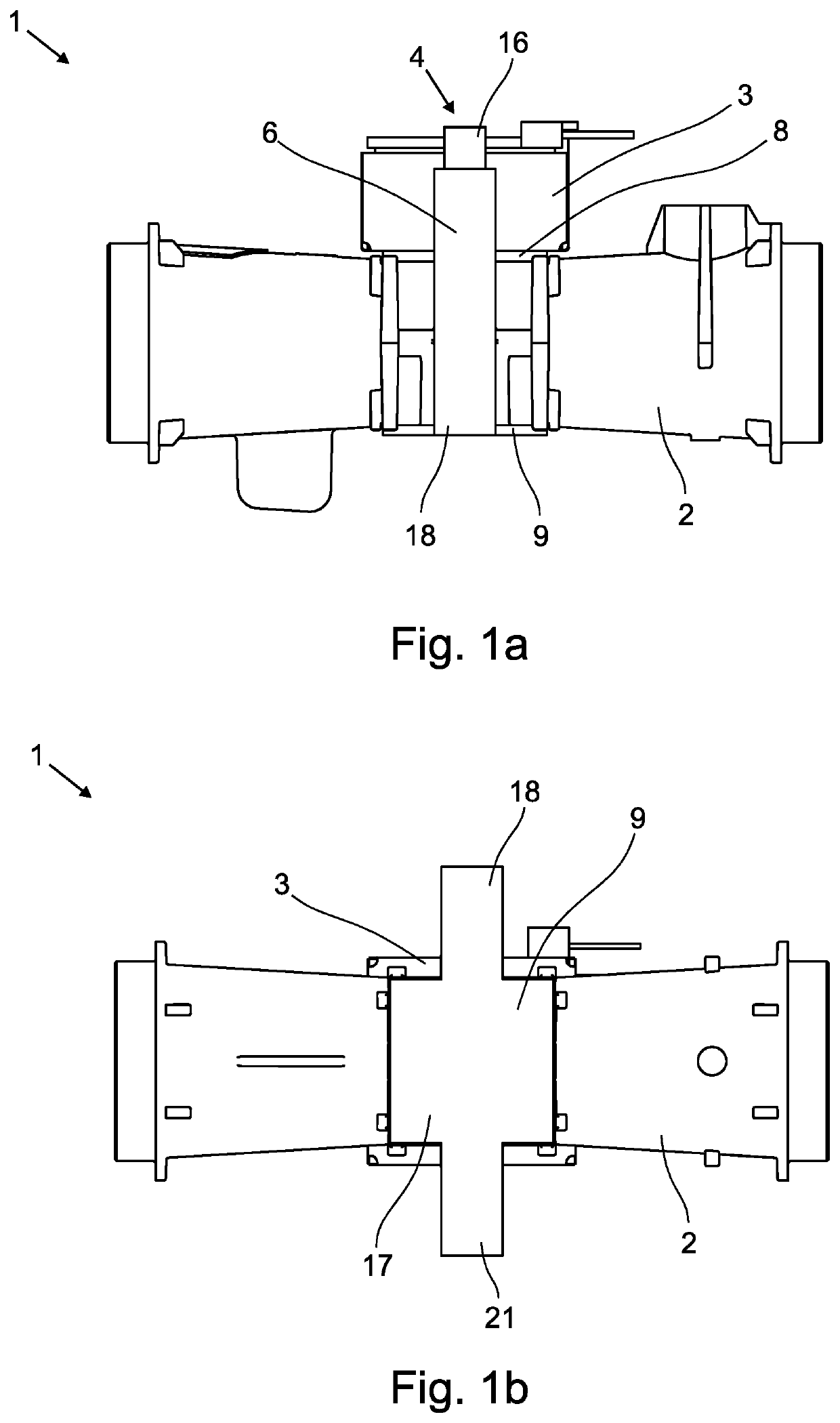
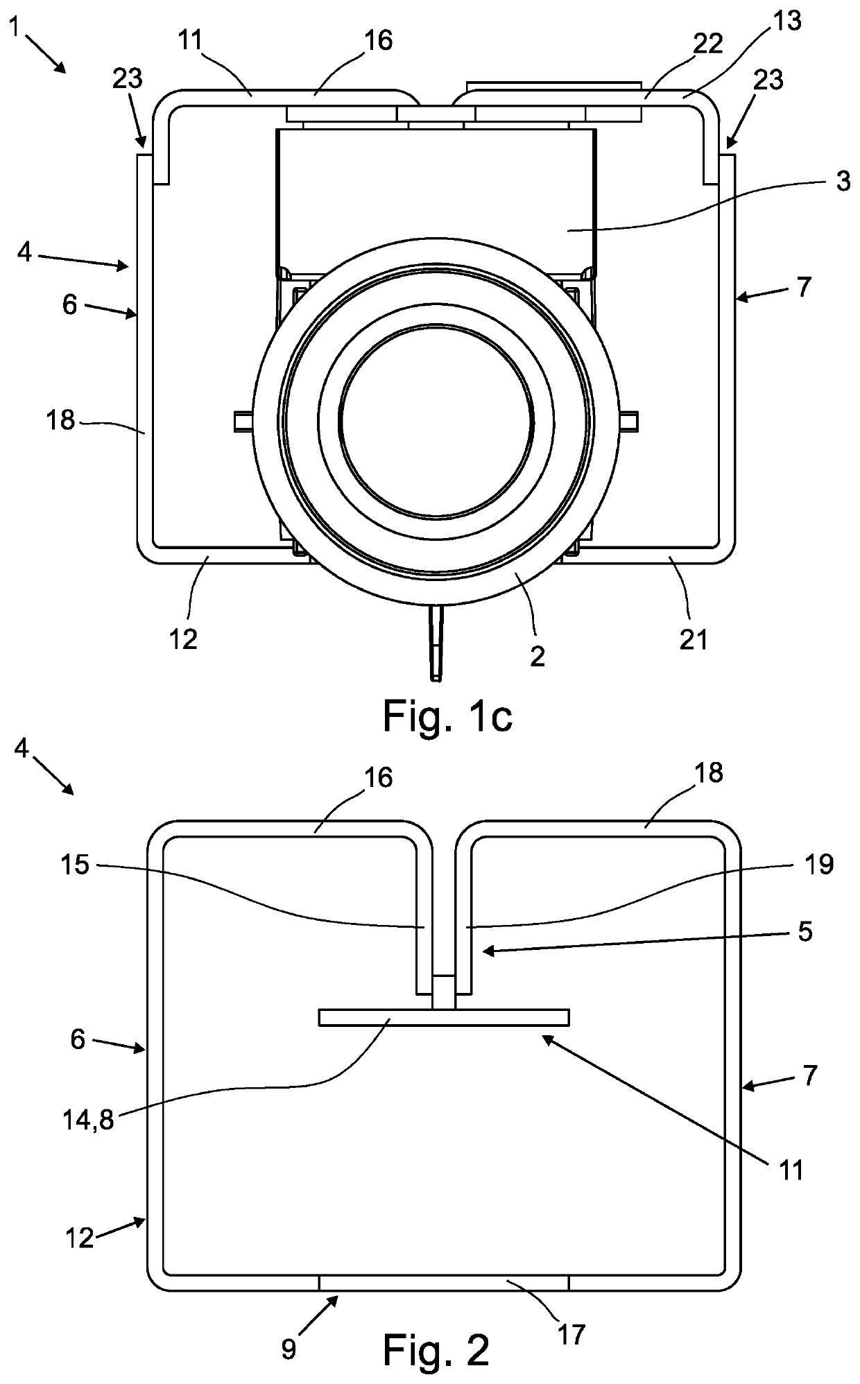
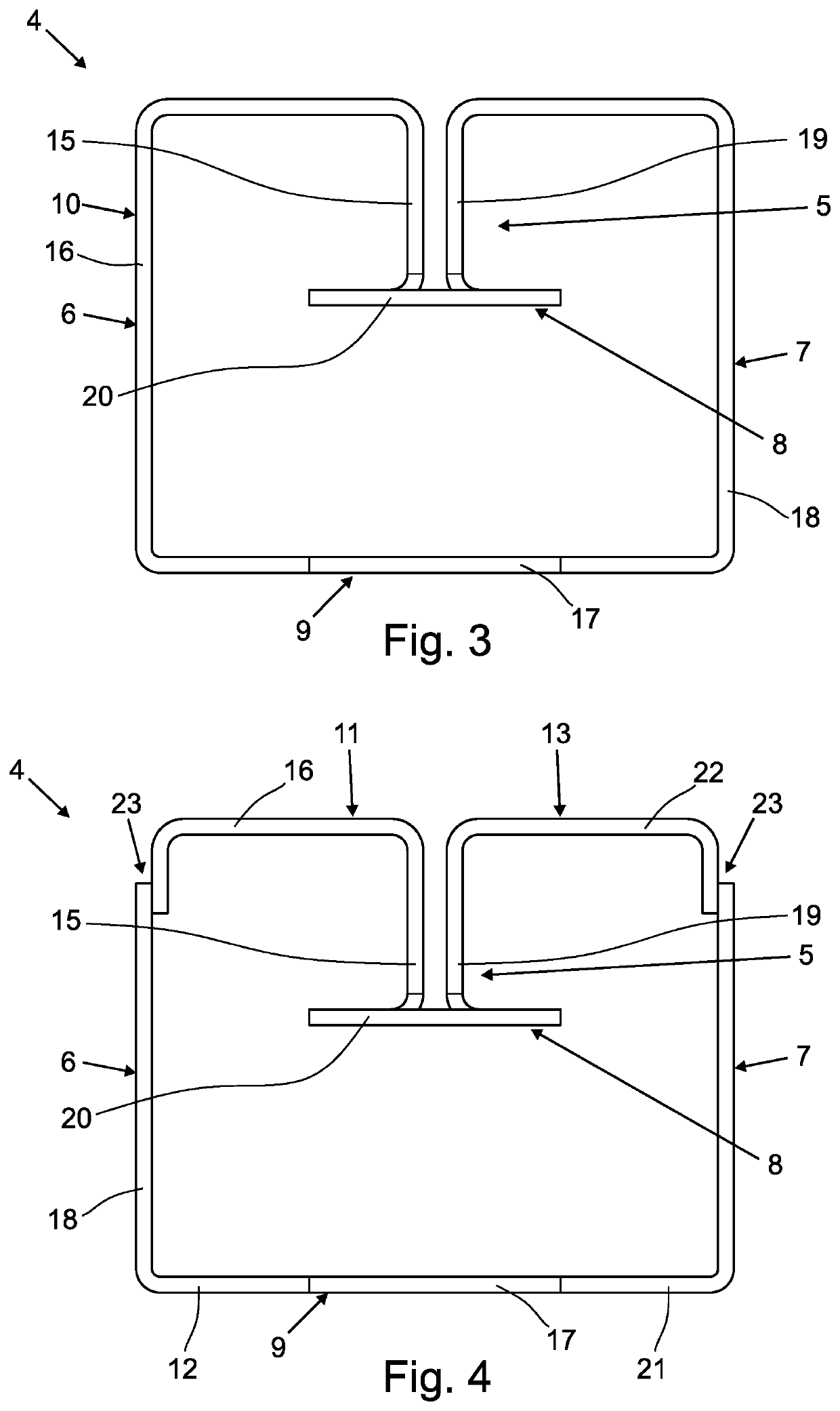
[0045]In FIGS. 1a to 1c, a magnetically-inductive flow-measuring device 1 is shown in various views. FIG. 1a shows the magnetically-inductive flow-measuring device 1 in a side view, FIG. 1b shows the magnetically-inductive flow-measuring device 1 from the bottom side, and FIG. 1c shows the magnetically-inductive flow-measuring device 1 in the direction of flow of the medium. The medium flows through the measuring tube 2 and is run through at least partially by a magnetic field, whereby the magnetic field is not depicted. The magnetic field is generated by a coil 3 and guided into the magnetic circuit device 4. The magnetic circuit device 4 has a coil core 5, a first yoke element 6, a second yoke element 7, a first pole piece 8 and a second pole piece 9. The coil core 5 of the magnetic circuit device 2 is the part that is located inside the coil 3 and surrounded by the windings of the coil 3. The yoke elements 6, 7 serve to guide the magnetic field lines, while the pole pieces 8, 9 c...


PUM


Abstract

A magnetically-inductive flow-measuring device, with a measuring tube for guiding an electrically-conductive medium, with a coil for generating a magnetic field that at least partially runs through the measuring tube and with a magnetic circuit device for guiding the magnetic field outside of the measuring tube, the magnetic circuit device has at least one coil core, a first yoke element, a second yoke element, a first pole piece and a second pole piece, the coil core is arranged inside the coil and the measuring tube is arranged between the first pole piece and the second pole piece. To provide a magnetically-inductive flow-measuring device with a magnetic circuit device, the magnetic circuit device is made from an at least partially bent sheet element or from multiple at least partially bent sheet elements.

Description

BACKGROUND OF THE INVENTIONField of the Invention[0001]The invention relates to a magnetically-inductive flow-measuring device, with a measuring tube for guiding an electrically-conductive medium, with a coil for generating a magnetic field that at least partially runs through the measuring tube, and with a magnetic circuit device for guiding the magnetic field outside of the measuring tube, whereby the magnetic circuit device has at least one coil core, a first yoke element, a second yoke element, a first pole piece and a second pole piece, whereby the coil core is arranged inside the coil and whereby the measuring tube is arranged between the first pole piece and the second pole piece. Moreover, the invention relates to a magnetic circuit device for a magnetically-inductive flow-measuring device, with at least one coil core, a first yoke element, a second yoke element, a first pole piece and a second pole piece, and a method for the production of a magnetic circuit device.Descript...

Claims


Application Information

Patent Timeline
Patent Type & Authority Patents(United States)
IPC IPC(8): G01F1/58
CPCG01F1/586G01F1/588
Inventor NEVEN, JOSEPH
Owner KRONE GMBH
Why Eureka
Try Eureka