Camera enclosure for harsh commercial environments and method for using same

Active Publication Date: 2022-03-22
DAHMES FORREST LEE
View PDF7 Cites 0 Cited by
  • Summary
  • Abstract
  • Description
  • Claims
  • Application Information

AI Technical Summary

Benefits of technology

[0008]The present invention relates to an enclosed camera apparatus for use in harsh applications such as those with high temperature and/or airborne powder. The apparatus includes a housing enclosing a camera, with air moving within the housing that cools the camera

Problems solved by technology

One challenge is when such cameras are used in harsh environments, including high heat an

Method used


Image

  • Camera enclosure for harsh commercial environments and method for using same
  • Camera enclosure for harsh commercial environments and method for using same
  • Camera enclosure for harsh commercial environments and method for using same

Examples


embodiment 10

Embodiment 10

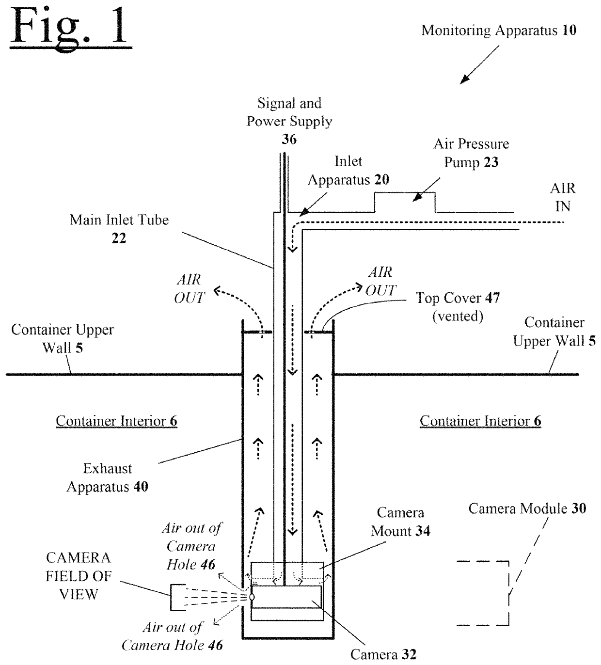
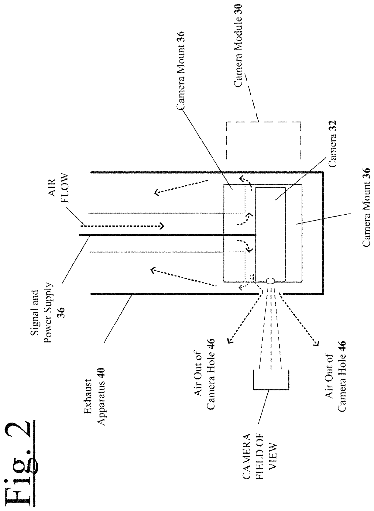
[0134]Reference is now made to FIGS. 1 and 2, which illustrate a Monitoring Apparatus 10 embodiment of the invention.

[0135]This Monitoring Apparatus 10 includes the following elements and features:[0136]5 Container upper wall[0137]6 Container interior[0138]10 Monitoring Apparatus[0139]20 Inlet Apparatus[0140]22 Main Inlet tube[0141]30 Camera Module[0142]32 Camera[0143]34 Camera mount[0144]36 Signal and power supply wiring[0145]40 Exhaust Apparatus[0146]46 camera hole[0147]47 top cover

[0148]The monitoring apparatus 10 basic elements include an inlet apparatus 20, camera module 30, and an exhaust apparatus 40. The camera module 30 is attached to the lower end of the inlet apparatus 20, and is located within the exhaust apparatus 40. Pressurized air is introduced into the inlet apparatus 20, which causes a predetermined air flow, such that the air then passes down through and adjacent the camera module 30, and then either passes out of a camera hole 46 in the exhaust appar...

embodiment 100

Embodiment 100

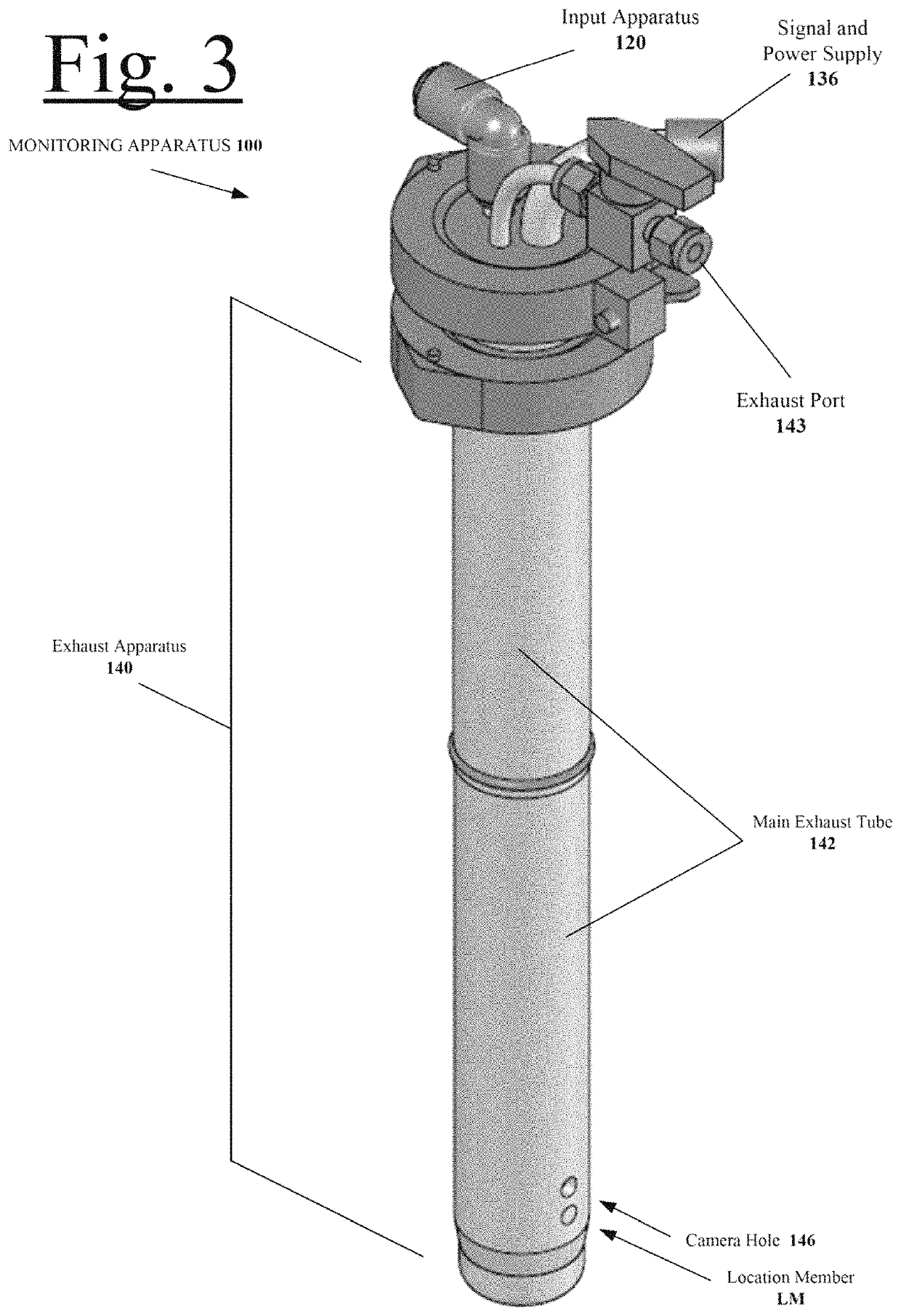
[0156]Reference is now made to FIGS. 3-10, which illustrate a Monitoring Apparatus 100 embodiment of the invention.

[0157]This monitoring apparatus 100 includes the following elements and features:[0158]100 Monitoring Apparatus[0159]120 Inlet Apparatus[0160]126 Inlet apparatus flange[0161]130 Camera Module[0162]132 Camera[0163]134 Camera mount[0164]136 Signal and power supply wiring[0165]137 Set Screw[0166]140 Exhaust Apparatus[0167]141 lower mounting flange (lower part of upper Tri-Clamp 150)[0168]142 main exhaust tube[0169]143 exhaust port[0170]144 side wall[0171]145 bottom end[0172]146 camera hole[0173]147 vented top cover (lower part of upper Tri-Clamp 150)[0174]148 base mounting flange (upper part of lower Tri-Clamp 160)[0175]149 container mounting flange (lower part of lower Tri-Clamp 160)[0176]150 Upper Tri-Clamp[0177]160 Lower Tri-Clamp

[0178]The monitoring apparatus 100 basic elements include an inlet apparatus 120, camera module 130, and an exhaust apparatus 14...

embodiment 200

Embodiment 200

[0190]Reference is now made to FIGS. 11-19, which illustrate a Monitoring Apparatus 200 embodiment of the invention.

[0191]This monitoring apparatus 200 includes the following elements and features:[0192]200 Monitoring Apparatus[0193]220 Inlet Apparatus[0194]222 Main Inlet Tube[0195]224 T-Fitting[0196]230 Camera Module[0197]232 Camera[0198]234 Camera mount[0199]236 Signal and power supply[0200]238 Front return groove[0201]239 Rear return groove[0202]240 Exhaust Apparatus[0203]241 Lower Mounting Flange (upper clamp)[0204]242 Main exhaust tube[0205]246 Camera hole[0206]247 vented top cover (lower part of upper Tri-Clamp 250)[0207]248 base mounting flange (upper part of lower Tri-Clamp 260)[0208]249 container mounting flange (lower part of lower Tri-Clamp 260)[0209]250 Upper Tri-Clamp[0210]260 Lower Tri-Clamp

[0211]The monitoring apparatus 200 basic elements include an inlet apparatus 220, camera module 230, and an exhaust apparatus 240. The camera module 230 is attached to...


PUM


Abstract

Disclosed is an enclosed camera apparatus for use in applications with high temperature and/or airborne powder. The apparatus includes a housing enclosing a camera, with air moving within the housing that cools the camera and pressurizes the housing such that some air expels through a camera outward viewing orifice (aka “camera hole”), such that the camera can look outwardly through the orifice without powder accumulating around and atop the camera lens and/or camera viewing orifice. The camera is held in place by a machined camera mount that centers the camera on the orifice and allows compressed air to pass over the camera and the cable to protect it from overheating. The machined camera mount allows compressed air to pass back through the rest of the housing after it cools the camera to cool the rest of the housing, including the power and signal supply lines of the camera, before it exhausts out the top. Also provided is a wiping apparatus that wipes accumulated powder from atop or around the camera viewing orifice.

Description

CROSS REFERENCE TO RELATED APPLICATION[0001]This application claims the full benefit and priority of provisional application No. 63 / 004,347, filed Apr. 2, 2020, entitled “CAMERA ENCLOSURE FOR HARSH COMMERCIAL ENVIRONMENTS AND METHOD FOR USING SAME”. The entire contents of this application are incorporated herein by reference.FIELD[0002]This disclosure relates to a camera enclosures for harsh commercial environments, and methods of using same.Introduction[0003]This section provides some introduction to various matters relating to the invention mentioned herein, but it should be understood that this should not be construed as prior art to the invention; certain materials may be included, referenced, or alluded to in this section that may be inventions of the inventors noted herein. This section is simply included to include some introduction for the sake of the reader, some of which may be background to the invention, and some which is not.[0004]Any reference to background herein is n...

Claims


Application Information

Patent Timeline
IPC IPC(8): H04N5/225G03B17/02G03B17/56G03B17/55G02B27/00
CPCH04N5/22521G02B27/0006G03B17/02G03B17/55G03B17/56H04N5/2252H04N5/2253H04N5/2254G03B37/005H04N23/52H04N23/51H04N23/55H04N23/54
Inventor DAHMES, FORREST LEE
Owner DAHMES FORREST LEE
Why Eureka
Try Eureka