
Vibrator device

a technology of vibrating device and drive force, which is applied in the direction of mechanical vibration separation, tactile signalling system, signalling system, etc., can solve the problem of not producing a large driving force, and achieve the effect of small size and large driving for

Active Publication Date: 2022-03-29
MURATA MFG CO LTD
View PDF16 Cites 0 Cited by
  • Summary
  • Abstract
  • Description
  • Claims
  • Application Information

AI Technical Summary

Benefits of technology

[0006]It is an object of the present invention to provide a vibrator device that is small in size and yet produces a large driving force.

Problems solved by technology

If such a vibrator device is reduced in size, it fails to produce a large driving force.

Method used


Image

  • Vibrator device
  • Vibrator device
  • Vibrator device

Examples


first embodiment

[0059]FIGS. 8 and 9 are schematic sectional views, corresponding to the sectional view of FIG. 2, illustrating the vibrator device when vibrating.

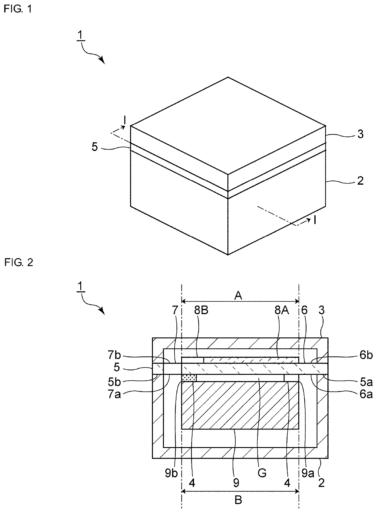
[0060]In FIG. 8, the first and second displacement plates 6 and 7 are displaced toward the first casing member 2. In FIG. 9, the first and second displacement plates 6 and 7 are displaced toward the second casing member 3. Unlike in the comparative example, the first and second displacement plates 6 and 7 are both connected to the added mass member 9 in this embodiment. The added mass member 9 thus vibrates to reciprocate on a path in a straight line in the direction in which the first and second casing members 2 and 3 are connected to each other. In the vibrator device 1, therefore, the first and second displacement plates 6 and 7 and the added mass member 9 vibrate almost in the entire region within the case. This can increase the vibration strength and also effectively reduce the size of the vibrator device 1.

[0061]If the vibrator devi...

third embodiment

[0082]FIG. 14 is a perspective view of an added mass member used in a vibrator device according to the present invention. FIG. 15 is a side view of this added mass member.

second embodiment

[0083]The shape of the surface of an added mass member 29A opposing the first and second displacement plates 6 and 7 is similar to that of the added mass member 29 used in the

[0084]That is, the added mass member 29A has tilting portions 29c and 29d on the surface opposing the first and second displacement plates 6 and 7. In the area of the added mass member 29A opposing the first displacement plate 6, the tilting portion 29c tilts toward the first displacement plate 6 as it advances from the central portion in the connecting direction of the first and second side portions 5a and 5b toward the second side portion 5b. Likewise, in the area of the added mass member 29A opposing the second displacement plate 7, the tilting portion 29d tilts toward the second displacement plate 7 as it advances from the central portion in the connecting direction of the first and second side portions 5a and 5b toward the first side portion 5a. The first and second tilting portions 29c and 29d may be prov...


PUM


Abstract

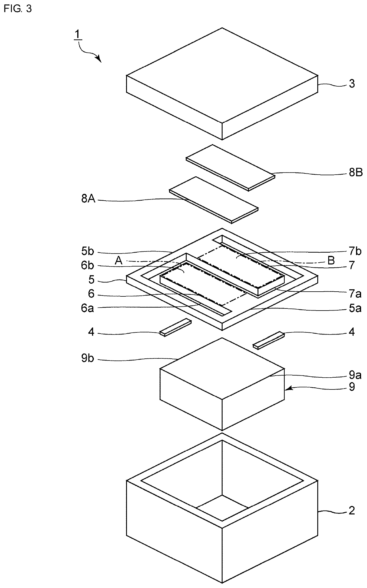
A vibrator device that includes a support member, first and second displacement plates, first and second piezoelectric vibrator elements, and an added mass member. The support member has first and second side portions opposing each other. The first displacement plate is supported by the first side portion and extends toward the second side portion so as to have a free end. The second displacement plate is supported by the second side portion and extends toward the first side portion so as to have a free end. The first and second piezoelectric vibrator elements are respectively disposed on the first and second displacement plates. The added mass member is connected to a portion of the first displacement plate at or around the free end thereof and to a portion of the second displacement plate at or around the free end thereof.

Description

CROSS REFERENCE TO RELATED APPLICATIONS[0001]The present application is a continuation of International application No. PCT / JP2018 / 032081, filed Aug. 30, 2018, which claims priority to Japanese Patent Application No. 2017-169174, filed Sep. 4, 2017, and Japanese Patent Application No. 2018-018894, filed Feb. 6, 2018, the entire contents of each of which are incorporated herein by reference.FIELD OF THE INVENTION[0002]The present invention relates to a vibrator device.BACKGROUND OF THE INVENTION[0003]Hitherto, various vibrator devices have been proposed as a vibrator device for a purpose such as informing a user of an incoming call. The following Patent Document 1 discloses an example of such a vibrator device. In the vibrator device disclosed in Patent Document 1, an elastic plate which is formed by bending a metal plate to have a U-like shape as viewed from the lateral side of the vibrator device is used. One side of the bending portion of this elastic plate is used as a planar fix...

Claims


Application Information

Patent Timeline
Patent Type & Authority Patents(United States)
IPC IPC(8): B06B1/06G08B6/00
CPCB06B1/0603G08B6/00B06B1/06
Inventor KAGAYAMA, KENJI
Owner MURATA MFG CO LTD
Learn More