Sheet supply device and sheet supply method

a technology of sheet supply and supply method, which is applied in the direction of transportation and packaging, thin material processing, function indicators, etc., can solve the problems of insufficient transmission of force from the lifting/lowering pressure roll to the standby side roll, difficulty in and the arm itself is bent, so as to achieve accurate transmission of force for joining the sheets. , the effect of reliably joining the sheets

Active Publication Date: 2022-03-29
ZUIKO CORP
View PDF13 Cites 0 Cited by
  • Summary
  • Abstract
  • Description
  • Claims
  • Application Information

AI Technical Summary

Benefits of technology

[0009]An object of the present invention is to provide a sheet supply device capable of reliably joining sheets by accurately transmitting force for joining the sheets.
[0012]According to the present invention, it is possible to reliably join the sheets by accurately transmitting the force for joining the sheets.

Problems solved by technology

Therefore, there is a possibility that the rotation arm is rotated around the rotation shaft due to force received from the lifting / lowering pressure roll, and the rotation arm itself is bent.
As a result, the transmission of the force from the lifting / lowering pressure roll to the standby side roll becomes insufficient, and it is difficult to reliably join the sheets.

Method used


Image

  • Sheet supply device and sheet supply method
  • Sheet supply device and sheet supply method
  • Sheet supply device and sheet supply method

Examples


Embodiment Construction

[0036]Hereinafter, embodiments of the present invention will be described with reference to the accompanying drawings. The following embodiments are specific examples of the present invention and do not limit the technical scope of the present invention.

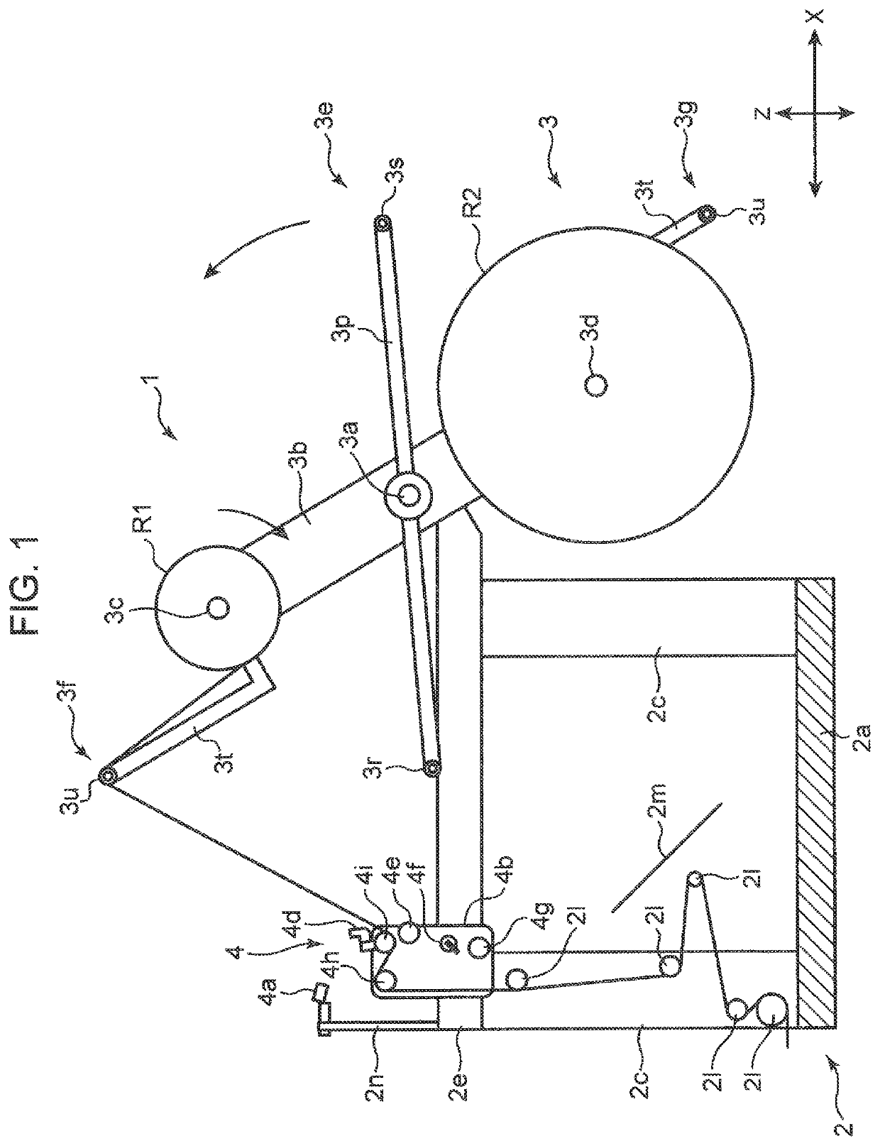
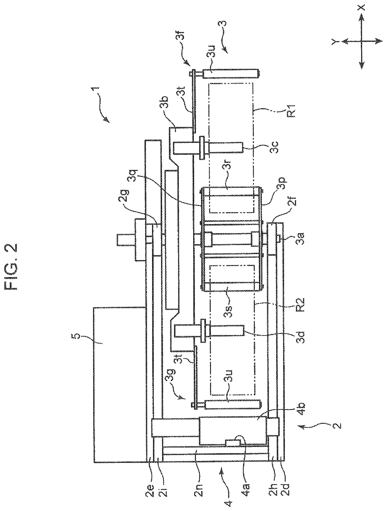
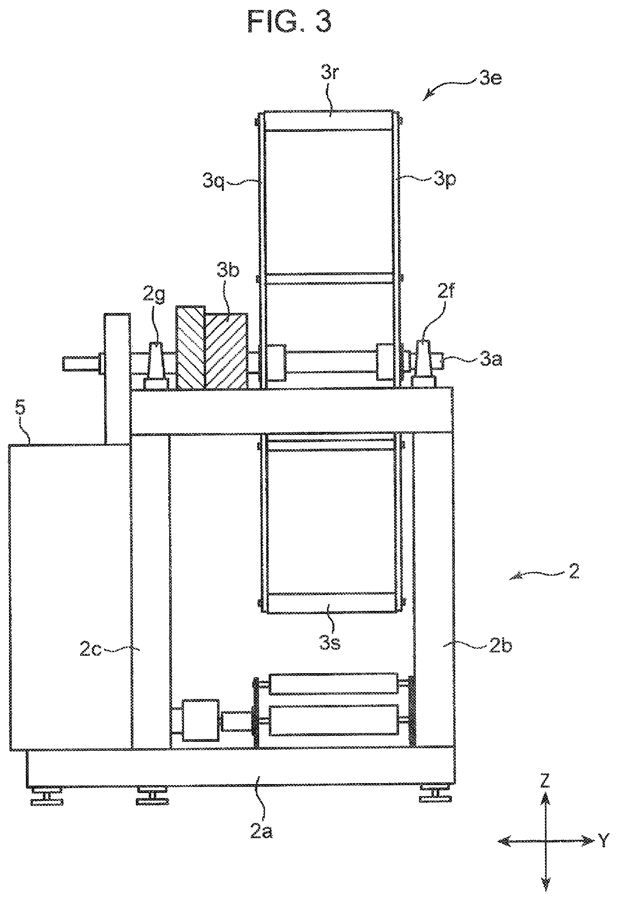
[0037]FIG. 1 is a partial front cross-sectional view of a sheet supply device 1 according to an embodiment of the present invention. FIG. 2 is a plan view of the sheet supply device 1 of FIG. 1. FIG. 3 is a side view of the sheet supply device 1 of FIG. 1. FIG. 4 is a rear view of the sheet supply device 1 of FIG. 1. Hereinafter, a horizontal direction in FIG. 1 will be described as an X direction, a vertical direction in FIG. 1 will be described as a Z direction, and a direction orthogonal to the X direction and the Z direction will be described as a Y direction.

[0038]Referring to FIGS. 1 to 3, the sheet supply device 1 is for supplying sheets from rolls R1 and R2 around which the sheets are wound.

[0039]Specifically, the sheet suppl...


PUM

PropertyMeasurementUnit
distanceaaaaaaaaaa
distanceaaaaaaaaaa
outer diameteraaaaaaaaaa

Abstract

Provided is a sheet supply device capable of reliably joining sheets by accurately transmitting force for joining the sheets. A joining mechanism includes a pressing roller that presses a sheet of a supply side roll against the outer peripheral surface of a standby side roll; and a moving unit that supports the pressing roller such that the pressing roller is configured to approach and move away from the standby side roll supported by a support shaft disposed at a splice position in the radial direction of the standby side roll. The moving unit supports the pressing roller such that the center of the pressing roller is movable on a straight line passing through the center of a rotation shaft and the center of the support shaft disposed at the splice position.

Description

TECHNICAL FIELD[0001]The present invention relates to a sheet supply device for continuously supplying a sheet from a roll around which the sheet is wound.BACKGROUND ART[0002]Conventionally, for example, an unwinding device described in Patent Literature 1 has been known.[0003]The unwinding device includes a rotation arm that is rotatably supported about a predetermined rotation shaft, a pair of chucking devices that is provided at a position away from the rotation shaft of the rotation arm in a direction orthogonal to the rotation shaft and holds respective rolls, and an automatic sheet joining device that joins a sheet of one roll (hereinafter, referred to as a supply side roll), which is supplying the sheet, to a sheet of the other roll (hereinafter, referred to as a standby side roll) among the rolls held on the chucking devices.[0004]The rotation arm can be rotated between a standby position where one chucking device is disposed at a position where a new roll is mounted, and a ...

Claims


Application Information

Patent Timeline
Patent Type & Authority Patents(United States)
IPC IPC(8): B65H19/18B65H21/00
CPCB65H19/18B65H21/00B65H2301/4621B65H2301/4631B65H2301/4633B65H2301/46152B65H2301/46172B65H2408/2411B65H2301/515323B65H19/1815B65H19/1868B65H2511/14B65H2220/01
Inventor TSUJIMOTO, YOSHIAKIFUJITA, HIDEKI
Owner ZUIKO CORP
Why Eureka
Try Eureka