Multidirectional display mount

a multi-directional display and mounting plate technology, applied in the direction of machines, mechanical equipment, stand/trestle, etc., can solve the problems of limited viewing and inability to provide comfortable viewing

Active Publication Date: 2022-03-29
MANEHU PROD ALLIANCE LLC
View PDF122 Cites 5 Cited by
  • Summary
  • Abstract
  • Description
  • Claims
  • Application Information

AI Technical Summary

Benefits of technology

[0004]At least some embodiments are directed to mounts capable of holding and moving objects. Mounted objects can be held at relatively high locations to keep the objects out of the way when stowed. Mounted objects can be conveniently moved to a desired position.
[0006]A mounting system, in some embodiments, comprises a multi-direction wall mount including a bracket configured to hold an object, a fixed support bracket couplable to a vertical support structure, and a multi-directional displacement apparatus. The displacement apparatus is movable to an expanded configuration and allows positioning of the object at different heights, viewing angles, and / or lateral positions. A biasing mechanism can facilitate movement of the object and, in some embodiments, can be in the form of a counterbalance mechanism. The counterbalance mechanism can facilitate manual movement of the object. In some embodiments, the displacement apparatus allows the object to be moved away from a raised position toward a lowered position along a path (e.g., a linear path, a multi-segment linear path, an arcuate path, a partially circular path, a curved path, a partially elliptical path, or the like).
[0009]The television mount device can have a three-dimensional range of motion defining a television positioning envelope through which the television can be moved. In some embodiments, the television mounting portion translates in a direction substantially parallel to a user applied force when the television is positioned within the television positioning envelope. This allows the user to conveniently direct and translate the television in any direction within the envelope.

Problems solved by technology

Unfortunately, if tilting wall mounts are installed at relatively high locations, there may be limited viewing because ideal viewing often requires that the center of the screen be level with a viewer's eyes.
If either a tilting wall mount or a horizontal motion wall mount is installed above a fireplace, the mounted television is often much higher than a sitting viewer's eyes and, thus, may not provide comfortable viewing.

Method used


Image

  • Multidirectional display mount
  • Multidirectional display mount
  • Multidirectional display mount

Examples


examples

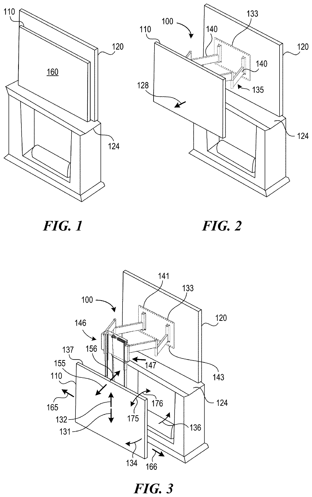
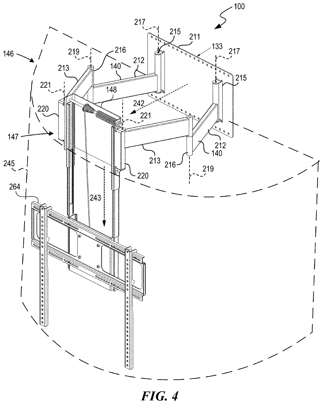
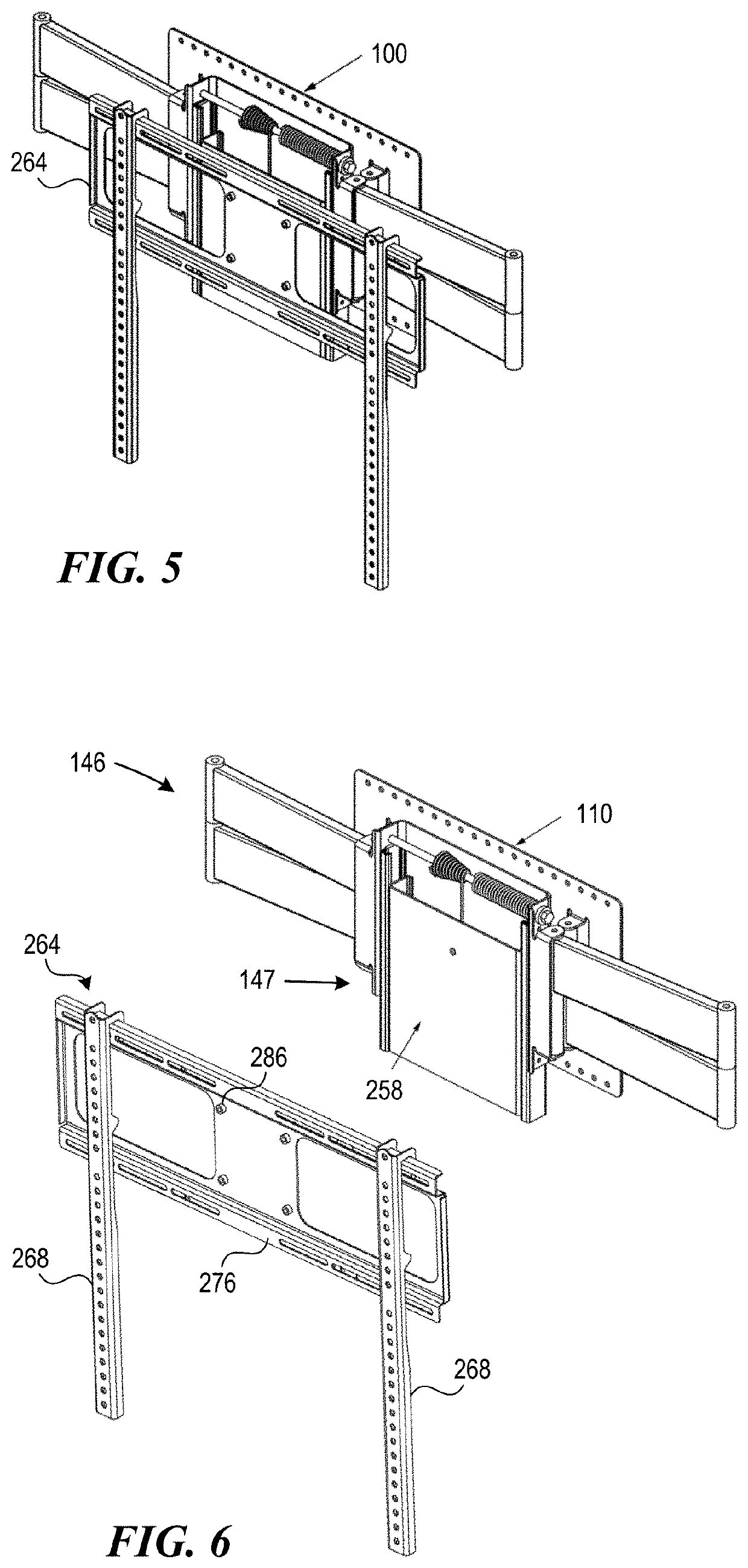
[0154]The present technology is illustrated, for example, according to various aspects described below. Various examples of aspects of the present technology are described as numbered examples (1, 2, 3, etc.) for convenience. These are provided as examples and do not limit the present technology. It is noted that any of the dependent examples can be combined in any suitable manner, and placed into a respective independent example. The other examples can be presented in a similar manner.[0155]1. A television mount device, comprising:[0156]a wall mounting portion;[0157]a television mounting portion configured to carry a television;[0158]an extender assembly coupled to the wall mounting portion and configured to move the television mounting portion away from and toward a vertical wall to which the wall mounting portion is coupled; and[0159]a vertical positioner mechanism coupled to the extender assembly and configured to vertically move the television mounting portion independent of op...


PUM


Abstract

A mounting system capable of mounting objects to support structures is disclosed. The mounting system includes a wall mount including a display bracket configured to hold the object, a fixed support bracket couplable to a vertical support structure, and a linkage assembly. The linkage assembly has a low-profile stowed configuration in which the object is held in a raised position close to the support structure. The linkage assembly moves to another configuration to move the object. The object can be held in a lowered position. A biasing mechanism can facilitate convenient movement of the object.

Description

CROSS-REFERENCE TO RELATED APPLICATION[0001]The present application claims the benefit under 35 U.S.C. § 119(e) of U.S. Provisional Patent Application No. 62 / 972,643, filed Feb. 10, 2020, which is incorporated herein by reference in its entirety.TECHNICAL FIELD[0002]The present invention relates generally to mounting systems. More specifically, the invention relates to multidirectional display mounts for mounting televisions to structures.BACKGROUND[0003]Televisions are often mounted directly to walls using wall mounts. Tilting wall mounts and horizontal motion wall mounts are two types of mounts that allow movement of the television. Tilting wall mounts often allow tilting about a horizontal axis of rotation. Unfortunately, if tilting wall mounts are installed at relatively high locations, there may be limited viewing because ideal viewing often requires that the center of the screen be level with a viewer's eyes. Horizontal motion wall mounts often allow movement of the television...

Claims


Application Information

Patent Timeline
Patent Type & Authority Patents(United States)
IPC IPC(8): F16M11/08F16M11/10F16M11/12
CPCF16M11/121F16M11/08F16M11/10F16M13/02F16M11/046F16M11/2014F16M11/2092F16M11/2085F16M2200/047F16M2200/061F16M11/18
Inventor NEWVILLE, BRIANMARC, LEE
Owner MANEHU PROD ALLIANCE LLC
Why Eureka
Try Eureka