
Lens device, lens system, imaging device, movable lens operation device, lens driving method, and lens driving program

a technology of movable lens and lens system, which is applied in the direction of printers, instruments, cameras focusing arrangement, etc., can solve the problem of not being able to intuitively ascertain the position of the focus lens during af control

Active Publication Date: 2022-03-29
FUJIFILM CORP
View PDF14 Cites 2 Cited by
  • Summary
  • Abstract
  • Description
  • Claims
  • Application Information

AI Technical Summary

Benefits of technology

[0006]As in JP2010-164637A and JP2011-138018A, the operation device for performing the MF control is caused to have a function of performing an instruction for switching between the AF control and the MF control, and thus it is possible to achieve the simplification of the lens system by dispensing with a dedicated member for this switching instruction.

Problems solved by technology

However, in JP2010-164637A and JP2011-138018A, since the position of the focus lens and the operation position of an operating member during the AF control are not linked to each other, it is not possible to intuitively ascertain the position of the focus lens during the AF control.

Method used


Image

  • Lens device, lens system, imaging device, movable lens operation device, lens driving method, and lens driving program
  • Lens device, lens system, imaging device, movable lens operation device, lens driving method, and lens driving program
  • Lens device, lens system, imaging device, movable lens operation device, lens driving method, and lens driving program

Examples


Embodiment Construction

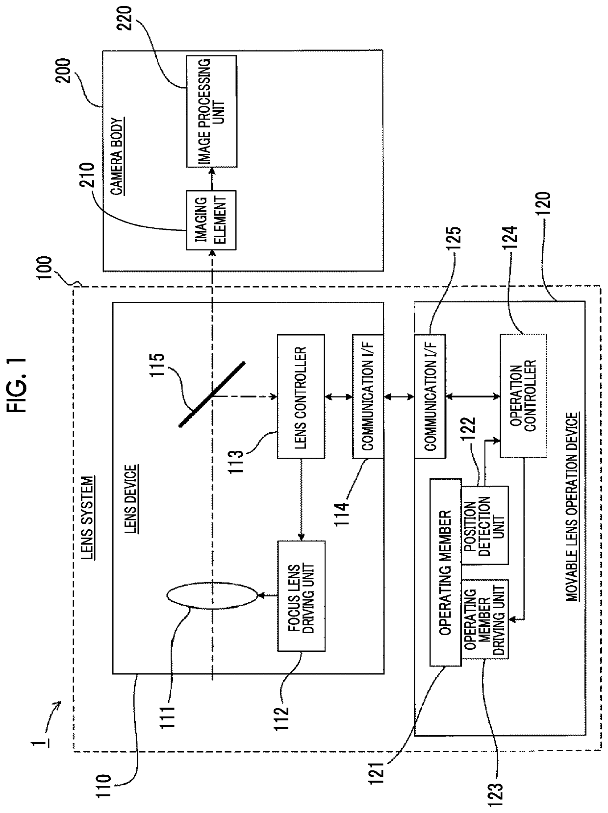
[0080]FIG. 1 is a diagram illustrating a schematic configuration of an imaging system 1 which is an embodiment of an imaging device of the present invention.

[0081]The imaging system 1 includes a lens system 100 and a camera body 200.

[0082]The lens system 100 includes a lens device 110 and a movable lens operation device 120.

[0083]The lens device 110 includes a focus lens 111, a focus lens driving unit 112, a lens controller 113, a communication interface (hereinafter, abbreviated to I / F) 114, and a half mirror 115.

[0084]The focus lens 111 is a movable lens capable of being moved in the direction of an optical axis. The focus lens refers to a lens that adjusts a focus position by moving the direction of the optical axis.

[0085]Meanwhile, although not shown in the drawing, the lens device 110 also includes other optical systems such as a lens, a stop and the like for forming a subject image in an imaging element 210. An imaging optical system of the lens device 110 is composed of the f...


PUM


Abstract

A lens device includes: a movable lens capable of being moved in a direction of an optical axis; a target position information acquiring unit that acquires information of a target position of the movable lens; a target position information transmitting unit that transmits the information of the target position to a movable lens operation device including a movable operating member for moving the movable lens and an operating member driving unit that drives the operating member; and a movable lens driving unit that performs first driving for moving the movable lens based on a position of the operating member detected by an operating member position detection unit that detects the position of the operating member, and the operating member driving unit drives the operating member based on the information of the target position.

Description

CROSS REFERENCE TO RELATED APPLICATION[0001]This is a continuation of International Application No. PCT / JP2017 / 003813 filed on Feb. 2, 2017, and claims priority from Japanese Patent Application No. 2016-070726 filed on Mar. 31, 2016, the entire disclosures of which are incorporated herein by reference.BACKGROUND OF THE INVENTION1. Field of the Invention[0002]The present invention relates to a lens device, a lens system, an imaging device, a movable lens operation device, a lens driving method, and a computer readable medium storing a lens driving program.2. Description of the Related Art[0003]A lens system is known which is provided with a lens device including a focus lens for changing a focus position movably in the direction of an optical axis, and an operation device for manually moving this focus lens. An example of the operation device includes a so-called focus demand or the like that moves a focus lens by rotating a rotatable operating member.[0004]In such a lens system, the...

Claims


Application Information

Patent Timeline
Patent Type & Authority Patents(United States)
IPC IPC(8): G02B7/09G02B7/10G02B7/04G03B3/10G02B7/28G02B7/08H04N5/232G02B7/34G03B5/00G03B3/12G03B13/20G03B13/36
CPCG02B7/09G02B7/04G02B7/08G02B7/102G02B7/28G02B7/34G03B3/10G03B3/12G03B5/00G03B13/20H04N5/23209H04N5/23212H04N5/23245H04N5/23296H04N5/232121H04N5/232122H04N5/232127G03B13/36G03B2205/0053H04N23/663H04N23/672H04N23/67H04N23/667H04N23/69H04N23/671H04N23/675
Inventor WADA, TETSU
Owner FUJIFILM CORP
Learn More