Resin multilayer substrate, actuator, and method of manufacturing resin multilayer substrate

a multi-layer substrate and actuator technology, applied in the field can solve the problems of positional deviation (or deformation) achieve the effects of reducing or preventing the positional deviation of the coil conductor pattern, reducing the loss of the coil conductor, and easy manufacturing of resin multi-layer substrates

Active Publication Date: 2022-03-29
MURATA MFG CO LTD
View PDF16 Cites 0 Cited by
  • Summary
  • Abstract
  • Description
  • Claims
  • Application Information

AI Technical Summary

Benefits of technology

[0006]Preferred embodiments of the present invention provide resin multilayer substrates which are each able to reduce conductor loss of a coil while reducing or preventing positional deviation of coil conductor patterns by regulating flow of resin at a time of hot pressing.

Problems solved by technology

If there are a plurality of coil conductor patterns with different line widths, the flow of the resin at the time of hot pressing may become irregular, with the result that positional deviation (or deformation) of the coil conductor patterns may be caused.

Method used


Image

  • Resin multilayer substrate, actuator, and method of manufacturing resin multilayer substrate
  • Resin multilayer substrate, actuator, and method of manufacturing resin multilayer substrate
  • Resin multilayer substrate, actuator, and method of manufacturing resin multilayer substrate

Examples


first preferred embodiment

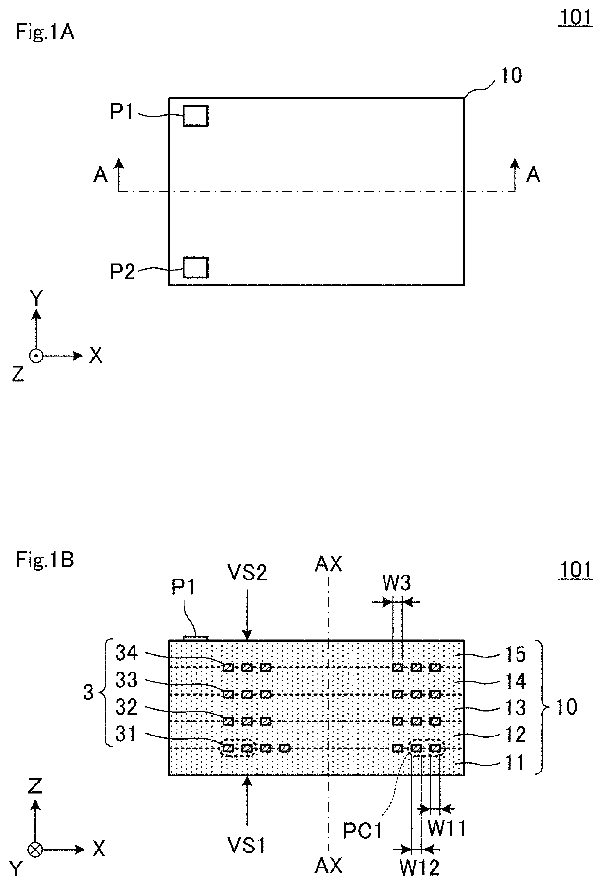
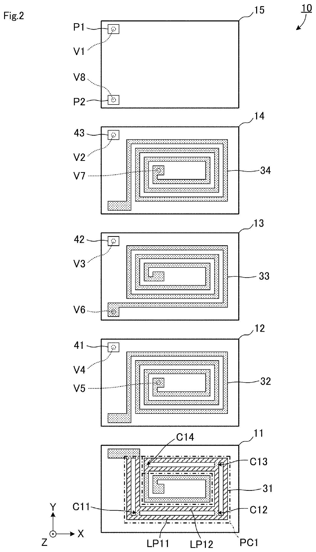
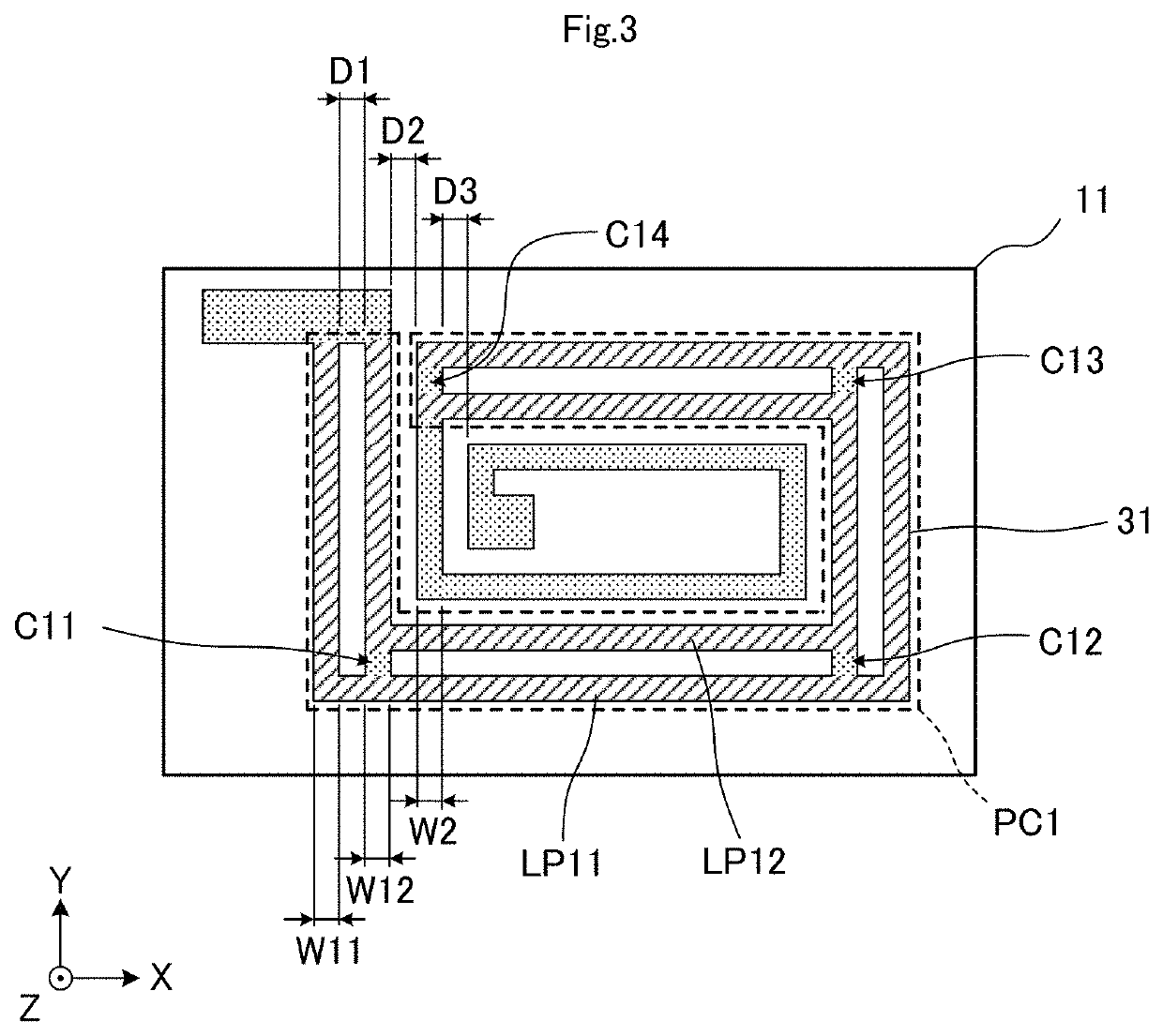
[0041]FIG. 1A is a plan view of a resin multilayer substrate 101 according to a first preferred embodiment of the present invention, and FIG. 1B is a sectional view taken along line A-A in FIG. 1A. FIG. 2 is an exploded plan view of a stacked body 10 included in the resin multilayer substrate 101. FIG. 3 is an enlarged plan view of a resin layer 11 defining a portion of the stacked body 10. In FIG. 2 and FIG. 3, coil conductor patterns 31, 32, 33, and 34 are shown by dot patterns in order to make the structure easy to understand. Further, in FIG. 2 and FIG. 3, linear conductor patterns LP11 and LP12 are shown by hatching.

[0042]The resin multilayer substrate 101 includes the stacked body 10, a coil 3 (described in detail later), input / output electrodes P1 and P2, and the like.

[0043]The stacked body 10 is a rectangular or substantially rectangular parallelepiped whose longitudinal direction coincides with an X-axis direction, and includes a first main surface VS1 and a second main sur...

second preferred embodiment

[0076]A second preferred embodiment of the present invention shows an example in which a plurality of coil conductor patterns including a parallel conductor portion are provided.

[0077]FIG. 5A is a plan view of the resin multilayer substrate 102 according to the second preferred embodiment, and FIG. 5B is a sectional view taken along line B-B in FIG. 5A. FIG. 6 is an exploded plan view of a stacked body 10A included in the resin multilayer substrate 102. In FIG. 5A and FIG. 6, coil conductor patterns 31a, 32a, 33a, and 34a are shown by dot patterns in order to make the structure easy to understand. Further, in FIG. 6, linear conductor patterns LP11, LP12, LP21, and LP22 are shown by hatching.

[0078]The resin multilayer substrate 102 is different from the resin multilayer substrate 101 according to the first preferred embodiment in that the resin multilayer substrate 102 includes the stacked body 10A and a coil 3A. Other elements and configurations of the resin multilayer substrate 102...

third preferred embodiment

[0089]A third preferred embodiment of the present invention shows an example in which a plurality of coil conductor patterns including a parallel conductor portion are arranged closest to the surface layers in the stacking direction of a plurality of resin layers.

[0090]FIG. 7A is a plan view of a resin multilayer substrate 103 according to the third preferred embodiment, and FIG. 7B is a sectional view taken along line C-C in FIG. 7A. FIG. 8 is an exploded plan view of a stacked body 10B included in the resin multilayer substrate 103. In FIG. 7A and FIG. 8, coil conductor patterns 31b, 32b, 33b, and 34b are shown by dot patterns in order to make the structure easy to understand. Further, in FIG. 7A and FIG. 8, linear conductor patterns LP11, LP12, LP41, and LP42 are shown by hatching.

[0091]The resin multilayer substrate 103 is different from the resin multilayer substrate 102 according to the second preferred embodiment in that the resin multilayer substrate 103 includes the stacked...


PUM

PropertyMeasurementUnit
widthaaaaaaaaaa
sizeaaaaaaaaaa
line widthsaaaaaaaaaa

Abstract

A resin multilayer substrate includes a stacked body including resin layers, and a coil including coil conductor patterns provided on two or more resin layers. The coil conductor patterns include a coil conductor pattern including a parallel conductor portion. The parallel conductor portion includes linear conductor patterns connected in parallel that are parallel to each other, and is provided at least at a portion of an outermost peripheral portion of the coil conductor pattern. A total line width of the linear conductor patterns of the parallel conductor portion is larger than a line width of other portions of the coil conductor pattern.

Description

CROSS REFERENCE TO RELATED APPLICATIONS[0001]This application claims the benefit of priority to Japanese Patent Application No. 2018-061883 filed on Mar. 28, 2018 and is a Continuation Application of PCT Application No. PCT / JP2019 / 010267 filed on Mar. 13, 2019. The entire contents of each application are hereby incorporated herein by reference.BACKGROUND OF THE INVENTION1. Field of the Invention[0002]The present invention relates to a resin multilayer substrate, and more particularly to a resin multilayer substrate including a stacked body including a plurality of resin layers and a coil that are stacked in the stacked body. Further, the present invention also relates to an actuator including the resin multilayer substrate, and a method of manufacturing the resin multilayer substrate.2. Description of the Related Art[0003]Conventionally, there have been known various resin multilayer substrates including a stacked body including a plurality of resin layers that are stacked and a coi...

Claims


Application Information

Patent Timeline
Patent Type & Authority Patents(United States)
IPC IPC(8): H02K3/26H02K41/025
CPCH02K3/26H02K41/025H02K2203/03H01F41/04H05K1/16H05K3/46H01F5/00H01F17/00H02K7/14H02K41/031
Inventor ITO, SHINGO
Owner MURATA MFG CO LTD
Why Eureka
Try Eureka