Structure of Phase Shifter and Mixer Based on Dielectric Integrated Suspension Line

A technology of dielectric integration and phase shifter, which is applied in the direction of waveguide devices, circuits, electrical components, etc., can solve the problems of large insertion loss and achieve the effects of small radiation loss, reduced dielectric loss, and reduced radiation loss

Active Publication Date: 2021-02-19
UNIV OF ELECTRONICS SCI & TECH OF CHINA
View PDF3 Cites 0 Cited by
  • Summary
  • Abstract
  • Description
  • Claims
  • Application Information

AI Technical Summary

Problems solved by technology

[0003] The technical problem to be solved by the present invention is to provide a phase shifter structure based on dielectric integrated suspension lines, to solve the problem of large insertion loss of the current commonly used phase shifter, and to design a low frequency conversion loss by using the phase shifter structure mixer structure

Method used


Image

  • Structure of Phase Shifter and Mixer Based on Dielectric Integrated Suspension Line
  • Structure of Phase Shifter and Mixer Based on Dielectric Integrated Suspension Line
  • Structure of Phase Shifter and Mixer Based on Dielectric Integrated Suspension Line

Examples


Embodiment 1

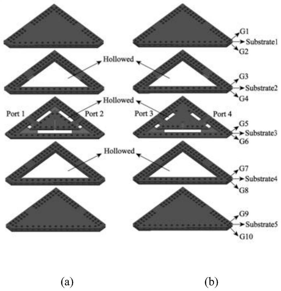
[0032] In this embodiment, by using a triangular patch structure, the larger surface area can reduce the conductor loss of the circuit. In addition, based on the processing platform of the dielectric integrated suspension line, the patch structure is placed inside the air cavity of the multi-layer dielectric board, and metallized holes and metal layers are used on the outer periphery to form a shielding environment, which can triangulate the radiation loss of the patch. In addition, the redundant dielectric of the circuit part is excavated to further reduce the dielectric loss of the circuit.

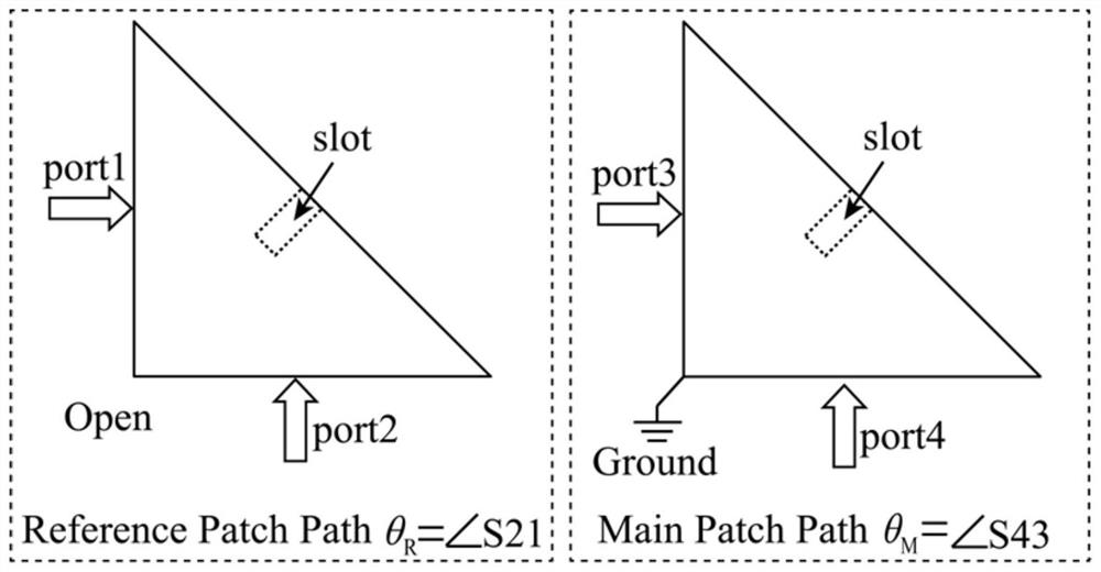
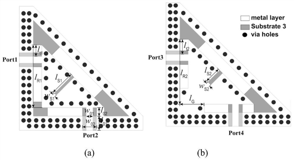
[0033] Such as figure 1 As shown in , the triangular patch phase shifter includes two triangular patch structures, each of which has a long slot structure on the hypotenuse. Wherein, the right-angle ground patch can be used as the main path of the phase shifter, and the right-angle open patch is used as the reference phase path of the phase shifter. The feed positions of the input and...

Embodiment 2

[0040] This embodiment proposes a mixer structure with low frequency conversion loss based on the phase shifter structure implemented in Embodiment 1. A mixer structure of this embodiment, such as Figure 5As shown, the mixer consists of a 90-degree coupler, a 90-degree phase shifter (main patch and reference patch), a matching network, a pair of Schottky diodes, and a low barrel filter. The local oscillator signal LO and the radio frequency signal RF are output from the two ports of the coupler (the two ports are isolated), respectively connected to the two paths of the 90-degree phase shifter, and then connected to the matching network (the role of the matching network is To achieve matching between different impedance terminals, to achieve better transmission performance). Both matching networks are connected to Schottky diodes, and the two diodes are in opposite directions. Finally, the two diodes are synthesized into one circuit, and output through the low-pass filter L...


PUM


Abstract

The invention discloses a phase shifter structure and a mixer structure based on dielectric integrated suspension lines. The two paths of the phase shifter both use a triangular patch structure, and the larger surface area can reduce the conductor loss of the circuit. In addition, based on the processing platform of the dielectric integrated suspension line, the patch structure is placed inside the air cavity of the multi-layer dielectric board, and metallized holes and metal layers are used on the outer periphery to form a shielding environment, which can triangulate the radiation loss of the patch. In addition, the redundant medium of the circuit part is excavated to further reduce the dielectric loss of the circuit; in addition, the present invention designs a mixer structure with low conversion loss by using the triangular patch phase shifter structure, which solves the problem of existing The technical problem of the large frequency conversion loss of the mixer.

Description

technical field [0001] The invention relates to the technical field of radio frequency microwave circuits, in particular to a phase shifter structure and a mixer structure based on dielectric integrated suspension lines. Background technique [0002] In RF microwave circuits, higher and higher requirements are put forward for circuit performance in terms of low loss, miniaturization, and high integration. A phase shifter is a passive circuit structure commonly used in radio frequency microwave circuits, and can be applied to antenna feed networks, beam scanning networks, and other phase shifting circuits. Commonly used types of passive phase shifters include Schiffman phase shifters, loaded open-circuit short-circuit stub phase shifters, and the like. Among them, the more commonly used Schiffman phase shifter is generally composed of coupling line stubs and transmission lines. Since narrow-side coupling is usually used, in the case of strong coupling, the requirements for ...

Claims


Application Information

Patent Timeline
Patent Type & Authority Patents(China)
IPC IPC(8): H01P1/18H01P1/213
CPCH01P1/18H01P1/213
Inventor 马凯学王勇强
Owner UNIV OF ELECTRONICS SCI & TECH OF CHINA
Why Eureka
Try Eureka