Image forming apparatus
- Summary
- Abstract
- Description
- Claims
- Application Information
AI Technical Summary
Benefits of technology
Problems solved by technology
Method used
Image

Examples
first exemplary embodiment
(1) Entire Structure and Operation of Image Forming Apparatus
(1.1) Entire Structure of Image Forming Apparatus
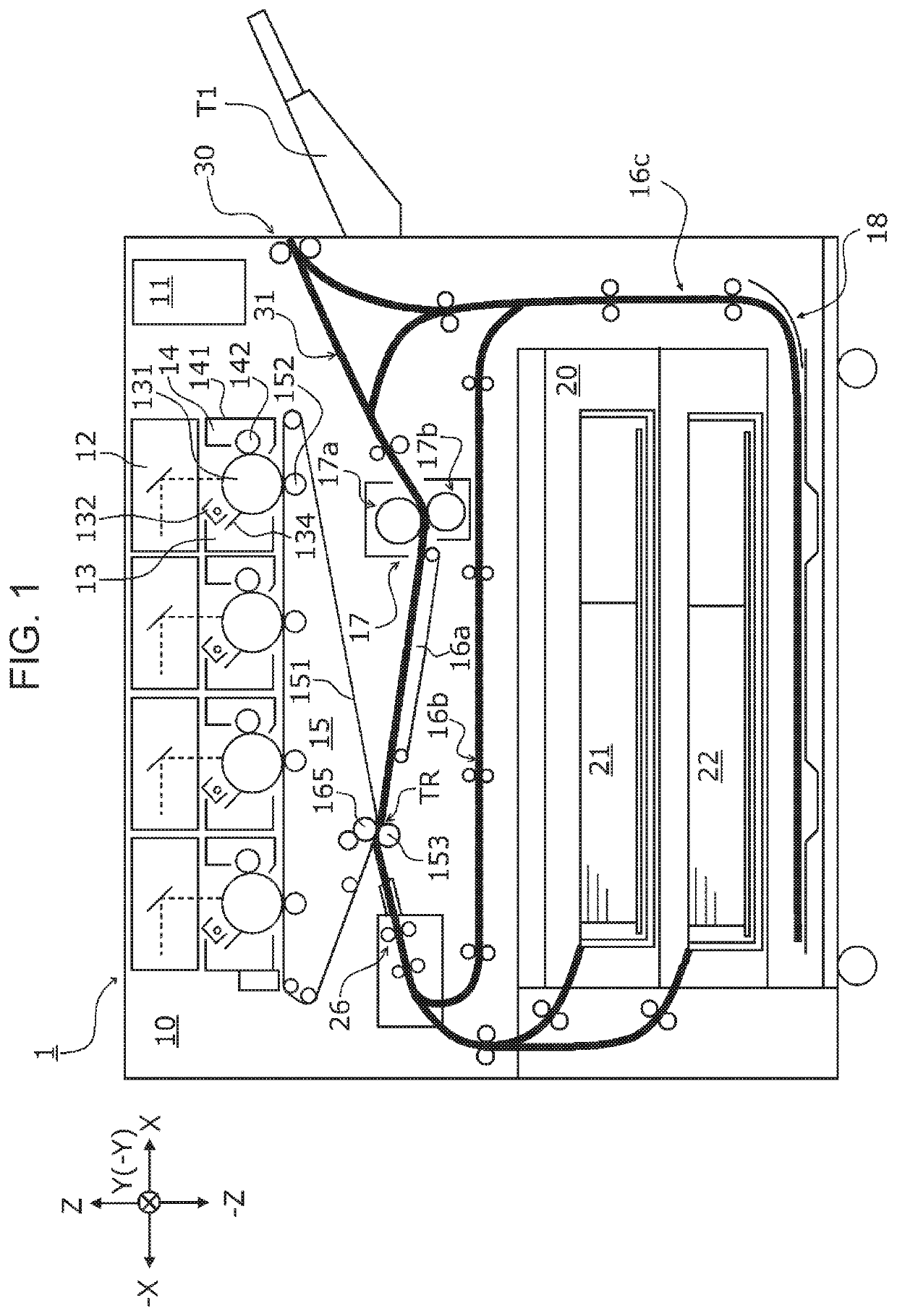
[0026]FIG. 1 is a schematic cross-sectional view of an example of a schematic structure of an image forming apparatus 1 according to the present exemplary embodiment.
[0027]The image forming apparatus 1 includes an image forming portion 10, a sheet feeder 20 attached to a lower portion of the image forming portion 10, and a sheet discharge portion 30 disposed at an end of the image forming portion 10 and to which printed sheets P are discharged.
[0028]The image forming portion 10 includes a system controller (not illustrated), an exposure device 12, a photoconductor unit 13, a developing device 14, a transfer device 15, a sheet transport device 16a, and a fixing device 17. The image forming portion 10 forms a toner image on a sheet P fed from the sheet feeder 20 from image information received from an image processing portion 40.
[0029]The sheet feeder 20, including sheet trays...
second exemplary embodiment
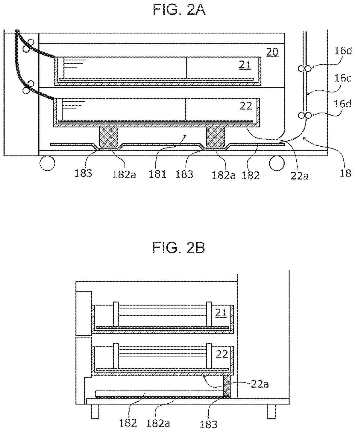
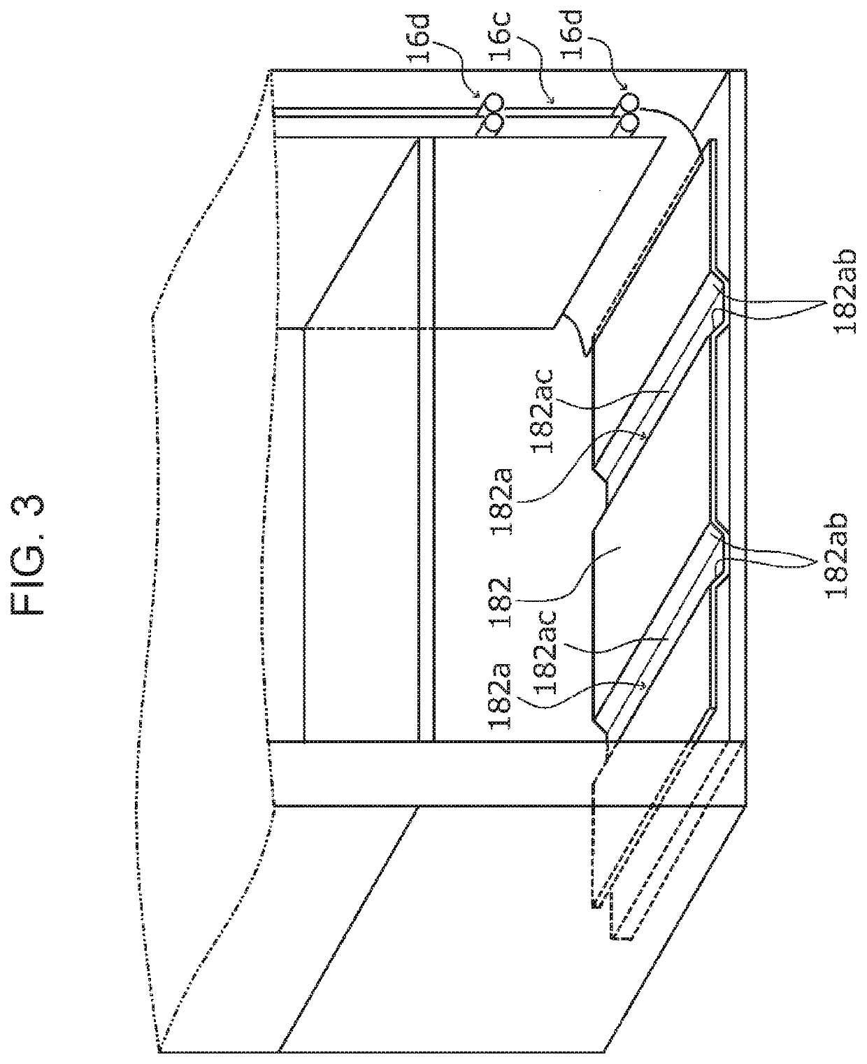
[0056]FIG. 6A is a schematic cross-sectional view of a sheet inverting unit 18A and sheet trays 21 and 22 according to a second exemplary embodiment viewed from the front, and FIGS. 6B and 6C are schematic cross-sectional views of the sheet inverting unit 18A and the sheet trays 21 and 22 viewed from the side. FIG. 7 is a perspective view of the sheet guide plate 182 and the sheet tray 22 viewed from the rear side of the apparatus. FIGS. 8A to 8C are schematic cross-sectional views, viewed from the side, of the sheet inverting unit 18A subjected to removal of the remaining sheet P1 and the sheet guide plate 182 subjected to cleaning.
[0057]Now, the structure of the sheet inverting unit 18A and cleaning of the sheet guide plate 182 will be described below with reference to the drawings.
[0058]As illustrated in FIG. 6A, the sheet inverting unit 18A of the image forming apparatus1 according to the present exemplary embodiment includes the sheet transport path 16c, into which the sheets P...
first modification example
[0066]FIG. 9 is a perspective view of a sheet guide plate 182 and a sheet tray 22 of a sheet inverting unit 18B according to a first modification example viewed from the rear side of the apparatus. FIGS. 10A and 10B are schematic cross-sectional views, viewed from the side, of the sheet inverting unit 18B subjected to removal of the remaining sheet P1 and the sheet guide plate 182 subjected to cleaning.
[0067]As illustrated in FIG. 9, projections 183B and second projections 184B of the sheet inverting unit 18B according to a first modification example are formed from Mylar (registered trademark) polyester films. Preferable examples of Mylar (registered trademark) polyester films include PET films having a thickness of 0.1 to 0.2 mm. As illustrated in FIGS. 10A and 10B, such Mylar (registered trademark) polyester films enable the projections 1833 to reliably push out the remaining sheet P1 left on the sheet guide plate 182 in association with the pull-out operation of the sheet tray 2...
PUM
| Property | Measurement | Unit |
|---|---|---|
| thickness | aaaaa | aaaaa |
| area | aaaaa | aaaaa |
| elastic | aaaaa | aaaaa |
Abstract
Description
Claims
Application Information
 - R&D
- Intellectual Property
- Life Sciences
- Materials
- Tech Scout
- Unparalleled Data Quality
- Higher Quality Content
- 60% Fewer Hallucinations
Browse by: Latest US Patents, China's latest patents, Technical Efficacy Thesaurus, Application Domain, Technology Topic, Popular Technical Reports.
© 2025 PatSnap. All rights reserved.Legal|Privacy policy|Modern Slavery Act Transparency Statement|Sitemap|About US| Contact US: help@patsnap.com