Elevator brake release monitoring

a technology for releasing brakes and elevators, applied in elevators, hoisting equipment, instruments, etc., can solve the problems of reducing affecting the service life of the brake, so as to reduce the wear of the brake, and be more reliable

Active Publication Date: 2022-04-05
KONE CORP
View PDF15 Cites 0 Cited by
  • Summary
  • Abstract
  • Description
  • Claims
  • Application Information

AI Technical Summary

Benefits of technology

[0009]A benefit of the invention is that it is able to guarantee that the brakes are opened because of the additional current. This helps reducing wearing of the brakes and also in fulfilling the regulations. A further benefit of the invention is that it is suitable for all kinds of. It may be applied to elevators that use counterweights of different weight but it works also in elevators without counterweight. A further benefit of the invention is that the solution is more reliable than conventional displacement sensors. Thus, conventional displacement sensors are not needed and this will lead into cost savings both in manufacturing and maintenance of an elevator.

Problems solved by technology

Sometimes a small failure in a part of the elevator may lead into severe security issues.
One of the important issues is that the elevator is operating without additional forces restricting the movement of the elevator car.
One possible cause is a defect brake that is not completely disengaged and causes friction.
The problem associated with this is the fact that the brake wears very fast and will not have the required braking power when it is needed.
The wearing may be very fast and the dangerous technical condition occurs so that the conventional inspection frequency is not able to notice wearing early enough.
These sensors are additional components that are not always reliable because the mechanical movement of a brake is very small.
Furthermore, sometimes the brake does not open completely but the sensor indicates that the brake has been opened but it still has a contact which will cause friction and leads into undesired wearing as discussed above.
A further drawback of additional sensor is that in general, using additional components causes expenses because of additional components and additional design needed.

Method used


Image

  • Elevator brake release monitoring
  • Elevator brake release monitoring
  • Elevator brake release monitoring

Examples


Embodiment Construction

[0014]Reference will now be made in detail to the embodiments of the present invention, examples of which are illustrated in the accompanying drawings.

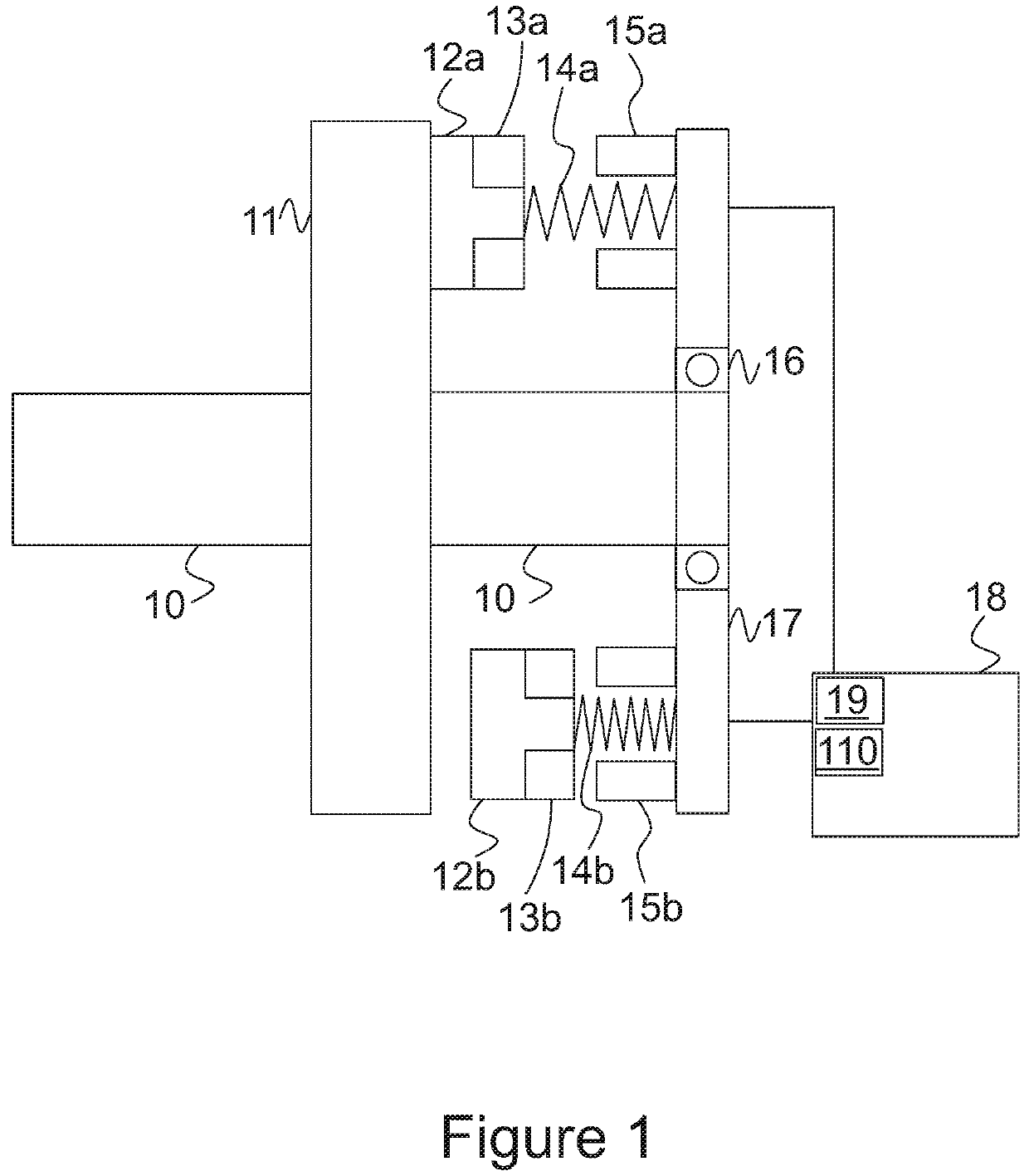
[0015]In FIG. 1 a block diagram of an arrangement according to the present invention. In the figure a traction sheave 11 is attached to a shaft 10 that is connected to the hoisting machine that is not shown in the figure, however, any conventional hoisting machine known to a person skilled in the art may be used.

[0016]In FIG. 1 an arrangement relating to brakes is discussed in more detail. In figure two independently operable brakes 12a-15a and 12b-15b are disclosed. The number of brakes in the example is two, however, any other number of brakes is acceptable for the present invention. Furthermore, one brake is enough to hold the elevator car, however, two, or even more, brakes are preferred and sometimes even required by regulations. Thus, in case of a brake failure in the first brake a second brake is still operable. In normal opera...


PUM


Abstract

It is desired that elevators are not operated when the brake is not completely released. Thus, the disengaging of brakes must be monitored or guaranteed otherwise. For providing guaranteed opening, the current for opening the brake is determined and then an additional current is provided to the brakes in order to guarantee the opening. The current for opening the brake is determined by doing a test sequence for each brake individually. In the test sequence, one brake is used to hold the elevator. Then, a momentum is applied to the elevator for moving the elevator car. The current is determined by increasing the current to the engaged brake gradually until the elevator moves. When the movement is detected, the current value is stored. When the elevator is operated regularly, the additional current is added to the stored value.

Description

FIELD OF THE INVENTION[0001]The invention relates elevators and particularly to braking systems used in elevators.BACKGROUND OF THE INVENTION[0002]Elevator systems are regulated all over the world. Regulations typically relate to the security of an elevator. Each elevator must fulfill the regulations and these requirements are sometimes verified regularly, for example yearly or monthly basis. Typically elevators are inspected regularly and parts not filling the requirements must be changed. As elevators are typically used for transporting passengers the security is an essential aspect. Thus, all aspects that can have a negative impact on the security should be eliminated. Sometimes a small failure in a part of the elevator may lead into severe security issues.[0003]One of the important issues is that the elevator is operating without additional forces restricting the movement of the elevator car. One possible cause is a defect brake that is not completely disengaged and causes frict...

Claims


Application Information

Patent Timeline
Patent Type & Authority Patents(United States)
IPC IPC(8): B66B1/32B66B5/00G01R19/00
CPCG01R19/0038B66B1/32B66B5/0031B66B5/0018B66D5/14
Inventor KATTAINEN, ARISTOLT, LAURI
Owner KONE CORP
Why Eureka
Try Eureka