Brake screw for surgical lighting systems

a technology for lighting systems and brake screws, applied in the direction of screws, threaded fasteners, rod connections, etc., can solve the problems of increasing brake pressure and accelerating wear of brake components, and achieve the effects of reducing the risk of screw based rivets, and improving wear properties

Active Publication Date: 2019-01-10
AMERICAN STERILIZER CO
View PDF0 Cites 0 Cited by
  • Summary
  • Abstract
  • Description
  • Claims
  • Application Information

AI Technical Summary

Benefits of technology

[0015]An advantage of the present invention is the provision of a brake screw that has improved wear properties.
[0016]Another advantage of the present invention is the provision of a brake screw having a brake member with increased braking surface area to eliminate the risk of screw based rivets damaging the mounting tube surface if the brake screws are overcompressed.
[0017]Still another advantage of the present invention is the provision of a brake screw having a brake member that reduces brake pressure, thereby reducing wear of the brake member and prolonging the life of the brake screw.
[0018]Still another advantage of the present invention is the provision of a brake screw having an assembly that allows the thickness of the brake member to be the limiting factor for brake screw wear, thereby improving the useful life of the brake screw.
[0019]Yet another advantage of the present invention is the provision of a brake screw having a brake member with a pre-curved braking surface, thereby eliminating the need for a break-in period where the braking surface must wear to match the curvature of a surface of a mounting tube or ring in order to maximize braking force.
[0020]These and other advantages will become apparent from the following description of illustrated embodiments taken together with the accompanying drawings and the appended claims.

Problems solved by technology

This attachment method requires an opening at the center of braking member 62, which increases brake pressure, thereby accelerating wear of braking member 62.

Method used


Image

  • Brake screw for surgical lighting systems
  • Brake screw for surgical lighting systems
  • Brake screw for surgical lighting systems

Examples


Embodiment Construction

[0040]The drawings shown herein are for the purpose of illustrating embodiments of the invention only and not for the purposes of limiting same. It should be appreciated that the features of each disclosed embodiment may be combined in configurations alternative to those illustrated herein. It is intended that all such alternative configurations come within the scope of the present invention.

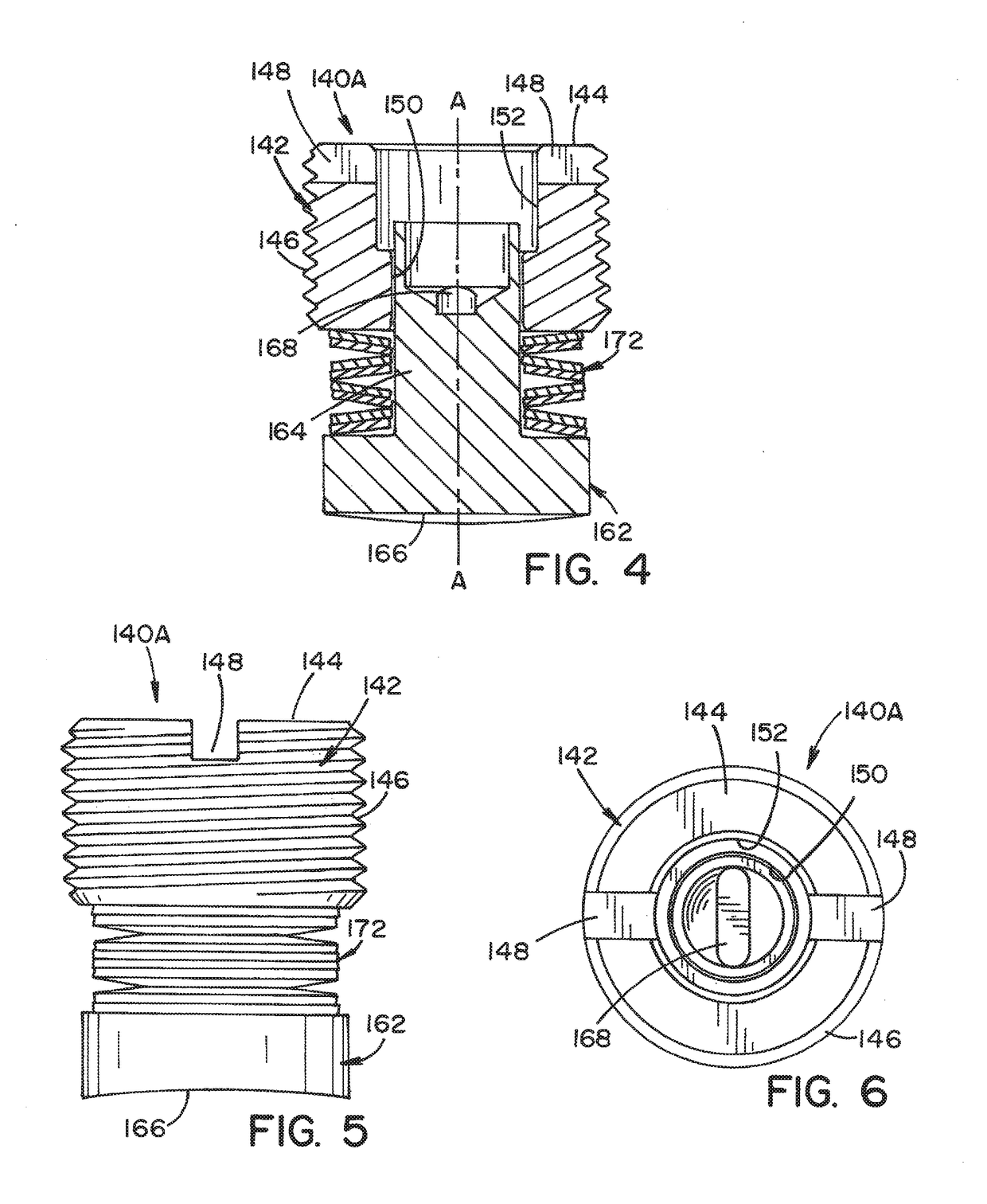
[0041]Several embodiments of a brake screw according to the present invention will be described in detail with reference to the FIGS. 4-18. As depicted in these drawings, the embodiments of the brake screw according to the present invention are generally comprised of a screw member, a brake member (e.g., a friction tip) having a braking surface, and a bias member (such as a spring).

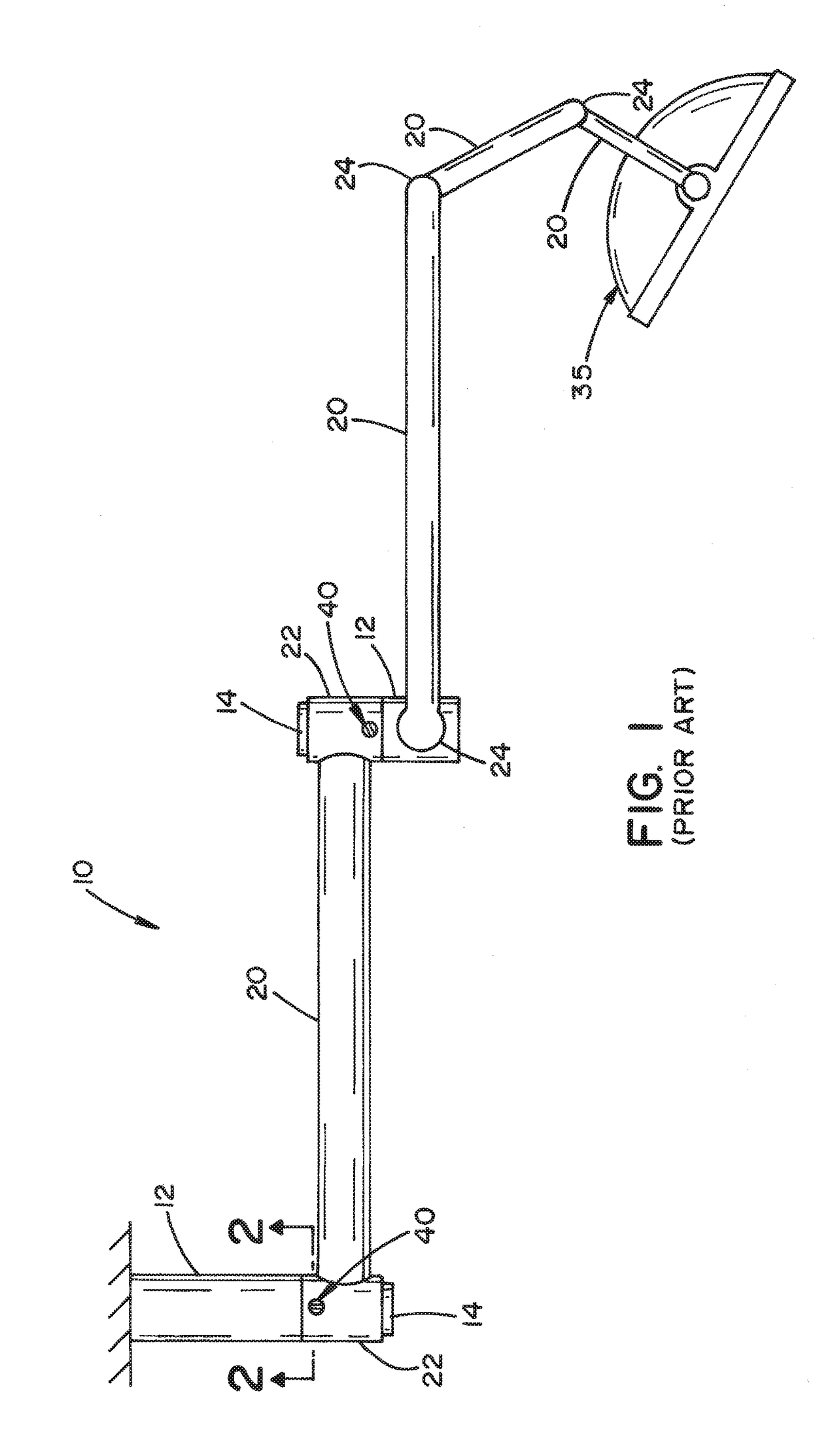
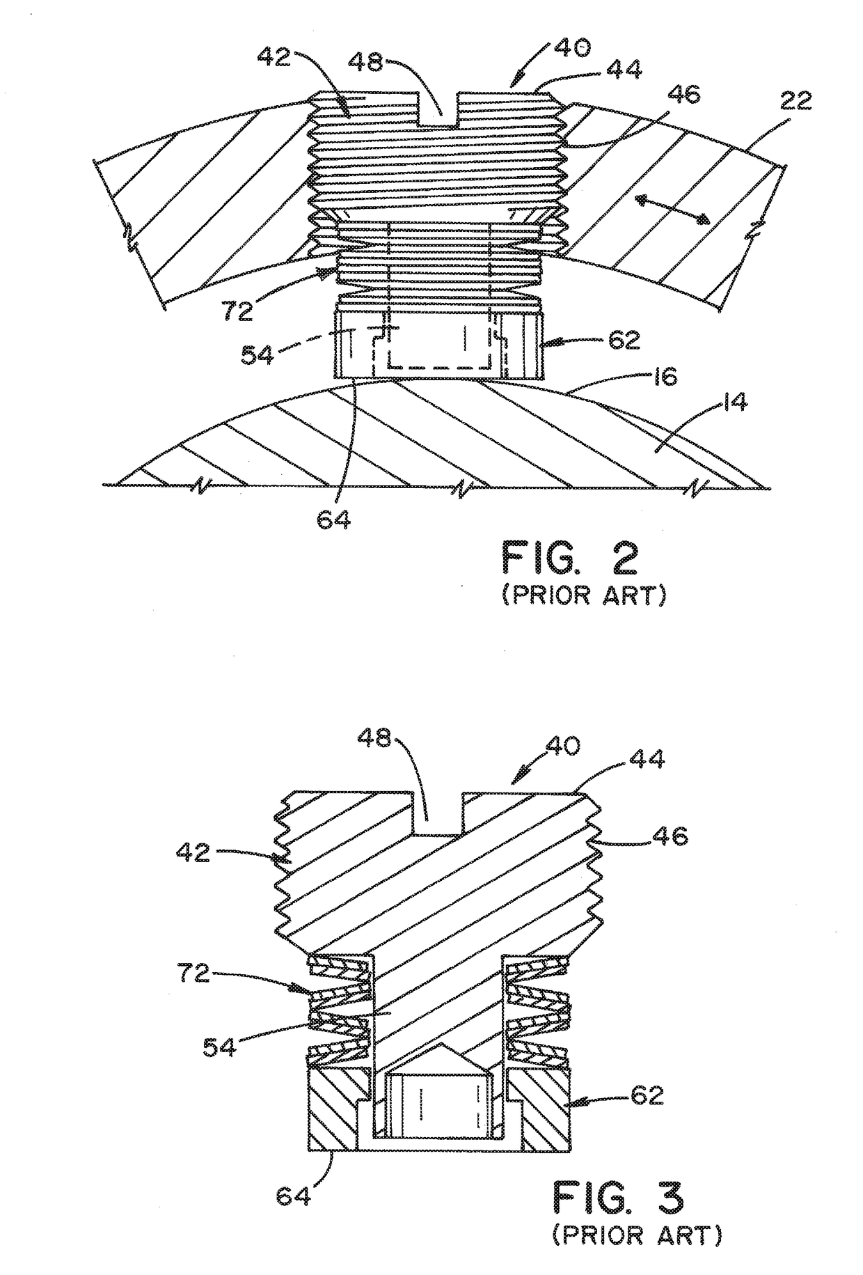
[0042]The embodiments of the brake screw shown in FIGS. 4-18 are implemented in accordance with a suspension for a surgical lighting system is depicted in FIGS. 1 and 2. The brake screw is used to control rotational b...


PUM


Abstract

A brake screw for use with a surgical lighting system. The brake screw includes a screw member retained within a threaded aperture of a mounting hub of a spindle of an arm used with the lighting system. The screw member is rotationally adjusted to enable displacement in an axial direction. A brake member is in axial alignment with the screw member and disposed for movement in the axial direction against a mounting tube retained within the mounting hub upon rotational adjustment of the screw member. A rivet section is integrally formed with the brake member and has a distal end retained within an axial recess formed within the screw member, allowing movement of the brake member in the axial direction within the screw member. A bias member is disposed between the screw member and the brake member to create a biasing force that urges apart the screw member and the brake member along the axial direction.

Description

RELATED APPLICATIONS[0001]This application claims the benefit of U.S. Provisional Application No. 62 / 530,468, filed Jul. 10, 2017, said provisional application is hereby fully incorporated herein by reference.FIELD OF THE INVENTION[0002]The present invention relates generally to an improved brake screw for use with surgical lighting systems.BACKGROUND OF THE INVENTION[0003]The majority of suspension systems for existing surgical lighting systems utilize mechanical radial braking devices in order to provide the required rotational performances of system components. The basic principle of these braking devices is that the force needed to achieve a desired level of friction / braking is applied in the radial direction (i.e., perpendicular to the axis of component rotation).[0004]FIG. 1 illustrates an exemplary existing suspension system 10 for a surgical lighting system. Suspension system 10 is generally comprised of spindles 12 and arms 20. Spindles 12 include a mounting tube or ring 14...

Claims


Application Information

Patent Timeline
Patent Type & Authority Applications(United States)
IPC IPC(8): F16D65/06F16D49/00
CPCF16D49/00F16D65/06F16D65/0971F16D2125/40F16B35/005F16B5/0266F16B7/18F16D59/02A61B90/35A61B2090/508
Inventor BELLOWS, LANCE CLARKHESER, MICHAEL JOSEPHMOHR, CHRISTOPHER ROYMOSS, BERNARD JOHNPICHLER, JERIME JOSEFTOTH, CRISTIAN LAURENTIU
Owner AMERICAN STERILIZER CO
Why Eureka
Try Eureka