
Circular saw that uses a prism to reflect the cut images

a circular saw and prism technology, applied in the field of circular saws, can solve the problems of inability to adjust the center of gravity, inability to see clearly, blurred front cover, etc., and achieve the effects of improving operation efficiency and convenience, ensuring use safety, and convenient for operators

Active Publication Date: 2022-04-12
DURQ MACHINERY
View PDF11 Cites 0 Cited by
  • Summary
  • Abstract
  • Description
  • Claims
  • Application Information

AI Technical Summary

Benefits of technology

The present invention is a circular saw with improved operation efficiency and convenience. One of the main technical effects is that the saw blade's cutting path is easily visible for the operator through a window on the front of the saw. This eliminates the need for the operator to tilt or lean forward to improve visibility, ensuring safety during use. Additionally, the saw includes an infrared generator that helps align and position the saw blade. The saw also has a transparent protective plate to safeguard the prism from damage during sawing. Additionally, the light source provides uniform and bright lighting for the sawing process. Overall, this circular saw provides better visibility, efficiency, and safety for the operator.

Problems solved by technology

However, the aforementioned arrangement causes the operator to use a roll or forward posture to view the movement through these windows.
However, such an operation posture is not only difficult to align with the cutting line, in addition, the side will have a slight error in the alignment of the viewing angle, but also may cause an unstable center of gravity and safety concerns during the operation.
However, after several operations, the high-temperature iron scraps from the saw will still cause the transparent front cover to blur and not be seen clear.

Method used


Image

  • Circular saw that uses a prism to reflect the cut images
  • Circular saw that uses a prism to reflect the cut images
  • Circular saw that uses a prism to reflect the cut images

Examples


Embodiment Construction

[0027]The applicant first states here that in the entire specification, including the preferred embodiments described below and the claims in the scope of patent application, the terms related to directionality are based on the directions in the drawings. Secondly, in the preferred embodiments and drawings to be described below, the same element numbers represent the same or similar elements or their structural features.

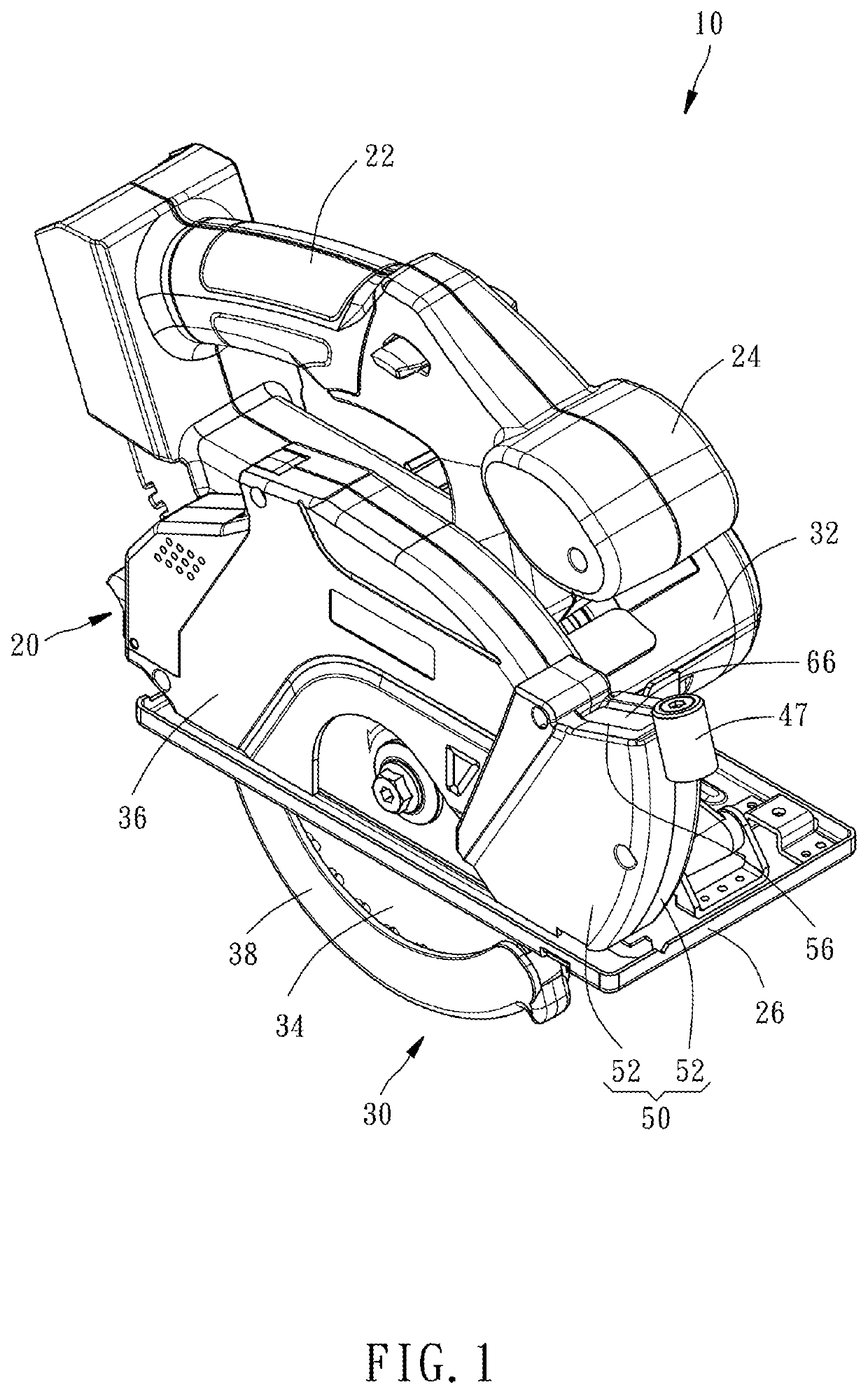
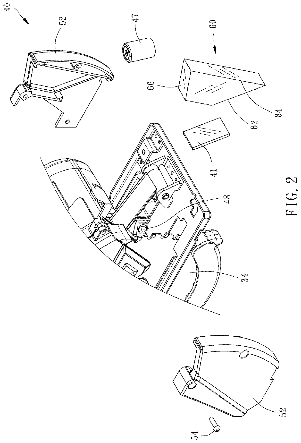
[0028]Referring to FIGS. 1 and 2, the circular saw 10 of the first preferred embodiment of the present invention takes a handheld circular saw as an example, which comprises a housing 20, a sawing assembly 30, and a prism assembly 40.

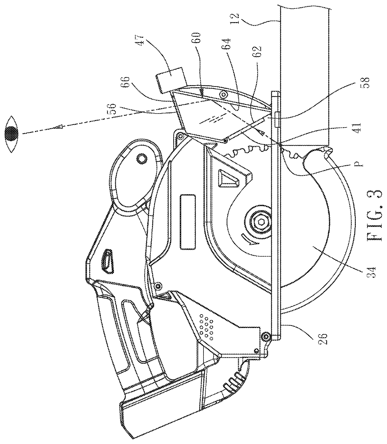
[0029]The housing 20 comprises a main grip 22 located on a top surface thereof, an auxiliary grip 24 located on the top surface in front of the main grip 22, and a bottom plate 26 located on an opposing bottom surface thereof for abutting the top surface of the workpiece 12 (as shown in FIG. 3).

[0030]The sawing assembly 30 comprises a mo...


PUM

PropertyMeasurementUnit
transparentaaaaaaaaaa
center of gravityaaaaaaaaaa
temperatureaaaaaaaaaa

Abstract

A circular saw includes a housing, a sawing assembly including a motor and a saw blade located at two opposite sides of the housing and connected together so that the saw blasé can be driven by the motor to saw the workpiece and a saw blade shield secured to the housing and covering a part of the saw blade to prevent the saw blade from cutting the surrounding people, and a prism assembly including a protective cover affixed to the front end of the saw blade shield and a prism located in the protective cover to reflect the image of the saw blade sawing the workpiece through a window of the protective cover to the line of sight of the operator. In this way, the operator can clearly confirm whether the sawing path is skewed with the normal operating posture to improve the efficiency.

Description

BACKGROUND OF THE INVENTION1. Field of the Invention[0001]The present invention relates to sawing machines and more particularly, to a circular saw that uses a prism to reflect the cut images.2. Description of the Related Art[0002]The conventional circular saw usually opens at least one window on the side of the protective cover, allowing the operator to confirm whether the sawing path is skewed through this window. However, the aforementioned windows are mostly located on the left and right sides of the saw blade. Related patent documents are seen in U.S. Pat. Nos. 7,219,434 or 6,543,143, etc. However, the aforementioned arrangement causes the operator to use a roll or forward posture to view the movement through these windows. However, such an operation posture is not only difficult to align with the cutting line, in addition, the side will have a slight error in the alignment of the viewing angle, but also may cause an unstable center of gravity and safety concerns during the ope...

Claims


Application Information

Patent Timeline
Patent Type & Authority Patents(United States)
IPC IPC(8): B23D45/16B23D59/00G02B17/04B27G19/04
CPCB23D59/003B23D45/16B27G19/04G02B17/04B23D47/00B23Q17/2404B27B9/00
Inventor LIU, CHIA-SHENGCHENG, YI-LILO, WEN-HUNG
Owner DURQ MACHINERY
Learn More