Silicone rubber and fiber-resin composite-based laminated product

a technology of composite-based laminated products and rubber, which is applied in the field of laminated products, can solve the problems of affecting the quality of laminated products, and reducing the service life of rubber shear bands, so as to improve the service life and reduce the cost of rolling. , the effect of reducing the number of rolls

Active Publication Date: 2022-04-12
MICHELIN & CO CIE GEN DES ESTAB MICHELIN
View PDF72 Cites 0 Cited by
  • Summary
  • Abstract
  • Description
  • Claims
  • Application Information

AI Technical Summary

Benefits of technology

[0020]Advantageously, the laminate of the invention, compared with the above laminates of the prior art, has proved in addition to contribute an at least equivalent stiffness to this shear band while conferring greater flexibility on the structure of the wheel, thus making it possible for it to take impacts better and absorb obstacles better.

Problems solved by technology

However, such a rubber shear band is not without disadvantages.
First of all, at the normal temperatures of use, for example between −30° C. and +40° C., it is relatively hysteretic, that is to say that a portion of the energy provided for the rolling is dissipated (lost) in the form of heat.
Subsequently, for in particular lower temperatures of use, such as those which may be found, for example, in geographical regions of polar type, typically below −50° C., indeed even lower, it is well known that a diene rubber, such as natural rubber, rapidly becomes weak and brittle and thus unusable.
Under such extreme conditions, it is understood, moreover, that more or less large and rapid fluctuations in temperature, combined, for example, with relatively high mechanical stresses, can also cause problems of adhesion between the two membranes and the shear layer, with a risk of localized buckling of the shear band at the membranes and an endurance in the end which is degraded.
Even if they have shown a high effectiveness, these laminates exhibit, however, the disadvantage of being relatively complex to manufacture and thus of having a high cost price, so much so that it was desirable to find an alternative which is less expensive and at least as effective, in particular for temperatures of use as broad as those indicated above.

Method used


Image

  • Silicone rubber and fiber-resin composite-based laminated product
  • Silicone rubber and fiber-resin composite-based laminated product
  • Silicone rubber and fiber-resin composite-based laminated product

Examples


Embodiment Construction

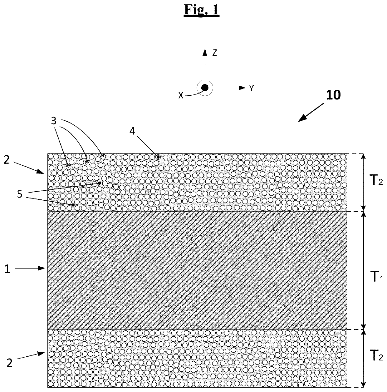
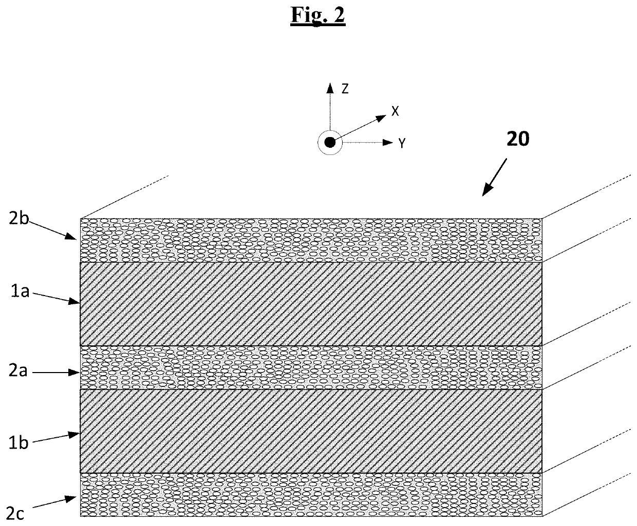
[0041]A first subject-matter of the present invention is thus a laminate (by definition multilayer) comprising at least one layer of silicone rubber sandwiched between two layers of fibre-resin composite comprising filaments of an inorganic substance embedded in a thermoset resin, in which the silicone layer has a thickness, denoted T1, of between 1.5 and 3 times the thickness, denoted T2, of each layer of fibre-resin composite, which is for its part between 0.25 and 2 mm.

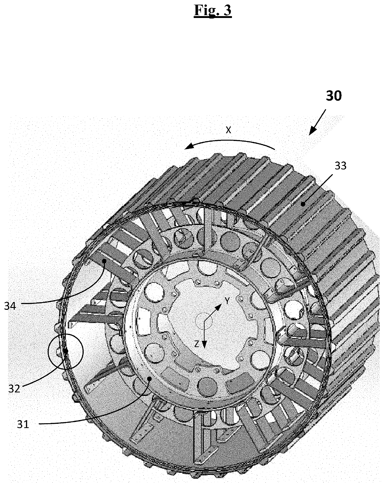
[0042]FIG. 1 illustrates, very simply and diagrammatically, an example of laminate (10) according to the invention, defining at least three main perpendicular directions, a longitudinal (that is to say, along the length) or circumferential (in the case of a non-planar laminate which is a constituent, for example, of a non-pneumatic wheel) direction (X), a transverse (that is to say, across the width) or axial (in the case of a non-planar laminate which is a constituent, for example, of a non-pneumatic wheel) direct...


PUM

PropertyMeasurementUnit
thickness T2aaaaaaaaaa
elongationaaaaaaaaaa

Abstract

A laminated product (10) comprises at least: a layer (1) of silicone rubber, in particular of the high temperature crosslinking type, such as, for example, a silicone rubber of VMQ or PVMQ grade the said layer (1) of silicone rubber being sandwiched between two layers (2) of fibre-resin composite comprising filaments (3) of an inorganic substance (4), in particular glass, embedded in a thermoset resin (5), such as, for example, a vinyl ester resin. The silicone layer has a thickness, denoted T1, of between 1.5 and 3 times the thickness T2 of each layer of fibre-resin composite, which is between 0.25 and 2 mm. Such a laminate may be used in the manufacture of a finished article, in particular of a non-pneumatic wheel or tire.

Description

1. FIELD OF THE INVENTION[0001]The present invention relates to laminated products, that is to say to products made of several layers of planar or non-planar shape which are connected together.[0002]The invention more specifically relates to laminated products, the specific construction of which makes it possible to obtain a deformable structure which can be used as beam resistant to flexural / compressive strains, these laminated products being in particular composites consisting, at least in part, of fibres coated in a resin matrix.[0003]The invention also relates to elastic (flexible) tyres or wheels for motor vehicles of the “non-pneumatic” type, that is to say not requiring an inflation gas, such as air, to assume their usable shape.2. STATE OF THE ART[0004]Elastic or flexible non-pneumatic tyres or wheels, that is to say tyres or wheels capable of deforming under a given stress and of returning to their initial shape once released from this stress, are well known to a person ski...

Claims


Application Information

Patent Timeline
Patent Type & Authority Patents(United States)
IPC IPC(8): B32B25/08B32B7/12B32B25/20B60B9/00B60C7/00B32B27/42B32B27/36B32B27/28B32B27/38B32B5/02B32B17/04B32B25/10B32B27/12B32B25/02B60B9/26
CPCB32B25/08B32B5/02B32B7/12B32B17/04B32B25/02B32B25/10B32B25/20B32B27/12B32B27/28B32B27/283B32B27/36B32B27/38B32B27/42B60B9/00B60C7/00B32B2250/03B32B2250/40B32B2260/021B32B2260/023B32B2260/046B32B2262/10B32B2262/101B32B2307/30B32B2307/50B32B2307/54B32B2307/732B32B2605/00B60B9/26
Inventor DELFINO, ANTONIOBERGUERAND, PHILIPPEPOZO, FRANÇOISSCHROETER, PASCAL
Owner MICHELIN & CO CIE GEN DES ESTAB MICHELIN
Why Eureka
Try Eureka