Electric lighting system with removably couplable power device

a power device and electric lighting technology, applied in the field of electric lighting systems, can solve the problems of unsightly wiring, time-consuming and unpleasant experience of users connecting wires to batteries, and lighting that needs plugging in lack aesthetics and freedom of movement, so as to save additional time for users, save time for users, and facilitate recharging and replacement.

Active Publication Date: 2022-04-19
VOLTRA LIGHTING LTD
View PDF30 Cites 2 Cited by
  • Summary
  • Abstract
  • Description
  • Claims
  • Application Information

AI Technical Summary

Benefits of technology

The patent describes electric lighting systems that can be easily recharged and replaced. These systems make it quick and easy for users to insert and remove power devices from lighting elements, allowing for quick and easy replacement. This saves time for users and allows for more efficient use of the lighting system. The "technical effect" of this patent is to overcome the limitations of earlier electric lighting systems and provide a more convenient, efficient, and flexible solution for users.

Problems solved by technology

Connecting wires to a battery or unscrewing components to insert a battery is a time-consuming and unpleasant experience for a user.
Lights that need plugging-in also lack the aesthetic and freedom of movement and requires unsightly wiring.
These problems are exacerbated when there are numerous lights to maintain.
If a restaurant includes a cordless light at every table, it may take employees significant time to individually plug in each light for charging.
If a restaurant includes a light with a cord, the cord may diminish the aesthetic of a cord-free table.
These electric lighting systems may save additional time for a user such as an employee of a hotel or restaurant that set a charged light in every room or at every table each night.

Method used


Image

  • Electric lighting system with removably couplable power device
  • Electric lighting system with removably couplable power device
  • Electric lighting system with removably couplable power device

Examples


Embodiment Construction

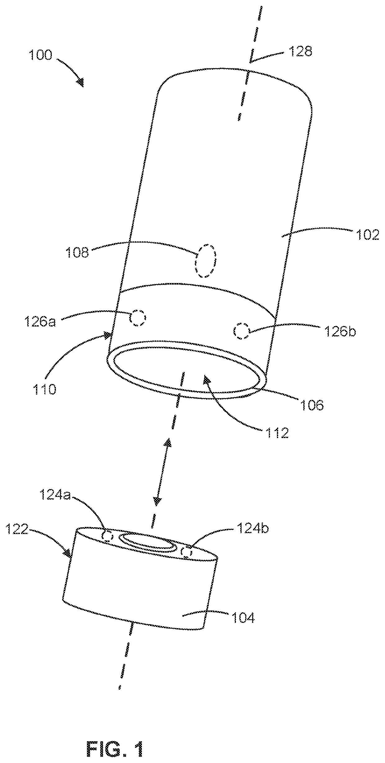
[0033]Users of lighting device may desire to use a lighting device without plugging the lighting device into a wall. For example, a restaurant may desire to place a lighting device on patrons' tables, without laying wires across the floor or the table. Additionally, lighting devices may benefit from the aesthetic of having no wire and practical benefit of not impeding limited space, such as at a restaurant table. Use of such mobile lighting devices may present challenges for powering the lighting devices.

[0034]Without receiving power directly from an electrical outlet of a wall, lighting devices may therefore include mobile power devices that retain charge to power the light without the need for plugging in to the wall while the lighting device is turned on. The lighting device will be able to turn on if it receives sufficient power from the power device. Eventually, the power device will transfer enough energy to the lighting device that it becomes depleted and cannot provide enoug...


PUM


Abstract

An example electric lighting system includes a lighting device that includes a housing including a lighting element and a power device holding portion. The power device holding portion includes a cavity. The cavity includes a first and a second electrical contact disposed within the cavity. The power device includes a third and a fourth electrical contact. The power device includes a coupling component. The coupling component is removably couplable to the power device holding portion such that an electrical communication is established when the power device is inserted into the cavity at any rotational position relative to the lighting device about a shared central axis. The power device is operable to power the lighting device through the electrical communication. The electrical communication is established between the first electrical contact and the third electrical contact and between the second electrical contact and the fourth electrical contact.

Description

BACKGROUNDField[0001]The present disclosure relates to electric lighting systems that have lighting elements such as LEDs and removably couplable power devices.Description of Related Art[0002]Current electrical lights require plugging-in, insertion of a battery, connecting wires, or unscrewing components. Connecting wires to a battery or unscrewing components to insert a battery is a time-consuming and unpleasant experience for a user. Lights that need plugging-in also lack the aesthetic and freedom of movement and requires unsightly wiring. These problems are exacerbated when there are numerous lights to maintain. For example, a hotel or a restaurant may require one or more lights for numerous rooms or dining tables. Also, plug-in options would require electrical connections for each table. If a restaurant includes a cordless light at every table, it may take employees significant time to individually plug in each light for charging. If a restaurant includes a light with a cord, th...

Claims


Application Information

Patent Timeline
Patent Type & Authority Patents(United States)
IPC IPC(8): F21V23/06F21L4/08F21V17/10H05B45/10F21Y105/10F21Y115/10
CPCF21V23/06F21L4/08F21V17/105H05B45/10F21Y2105/10F21Y2115/10F21S6/00F21V21/06F21V17/002F21S9/02
Inventor GUEDEZ, BAPTISTE ROBINROSS, TIMOTHY JAMES ALEXANDER
Owner VOLTRA LIGHTING LTD
Why Eureka
Try Eureka