
Device for monitoring vehicle occupant(s)

a technology for monitoring devices and vehicle occupants, applied in the direction of instruments, color televisions, television systems, etc., can solve the problems of tight manufacturing tolerance requirements, reduced performance, and difficulty in producing single laser and diffractive optical elements, and achieve stable base for optical components and effective heat dissipation

Active Publication Date: 2022-04-19
GENTEX CORP
View PDF13 Cites 0 Cited by
  • Summary
  • Abstract
  • Description
  • Claims
  • Application Information

AI Technical Summary

Benefits of technology

[0006]In particular, a vehicular monitoring device that is mounted in the roof of a vehicle must be capable of imaging an entire field of view of an interior of a vehicle. This field of view is typically a hemisphere. When the device operates by projecting two laser patterns onto the interior of the vehicle, each laser pattern is projected onto an area covering 60×90 degrees, thus covering together 120×90 degrees. Each laser projector thus covers only a portion (60×90 degrees) of the 180 degree field of imaging. This design overcomes the need to produce an extremely large coverage diffractive optical element. It is difficult to produce a single laser and diffractive optical element capable of covering a large field of view. This difficulty stems from two reasons. First, it is challenging to produce a diffractive optical element that is able to diffract the laser pattern across such an angular span of a typical passenger vehicle, while simultaneously preserving eye safety limits. In particular, increasing the field of view for diffractive optical elements may result in tighter requirements for manufacturing tolerances. Due to manufacturing limitations, such requirements might cause reduced performance, such as an increase in the amount of light that is transmitted in the diffractive optical element's zero-order power (i.e., without any diffraction), which leads to a violation of eye safety limits. Second, the structured light source, such as a laser, in such a system consumes a relatively large amount of power, and generates excess heat.
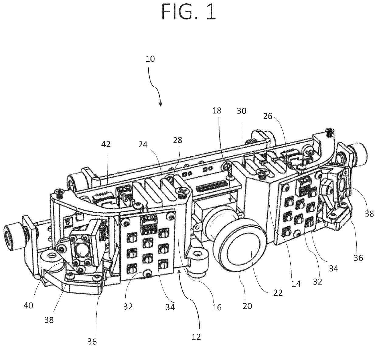
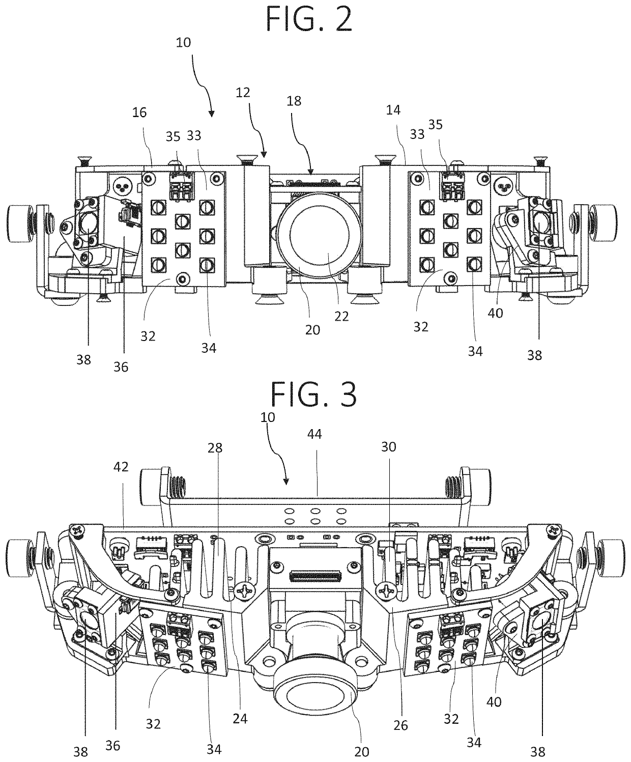
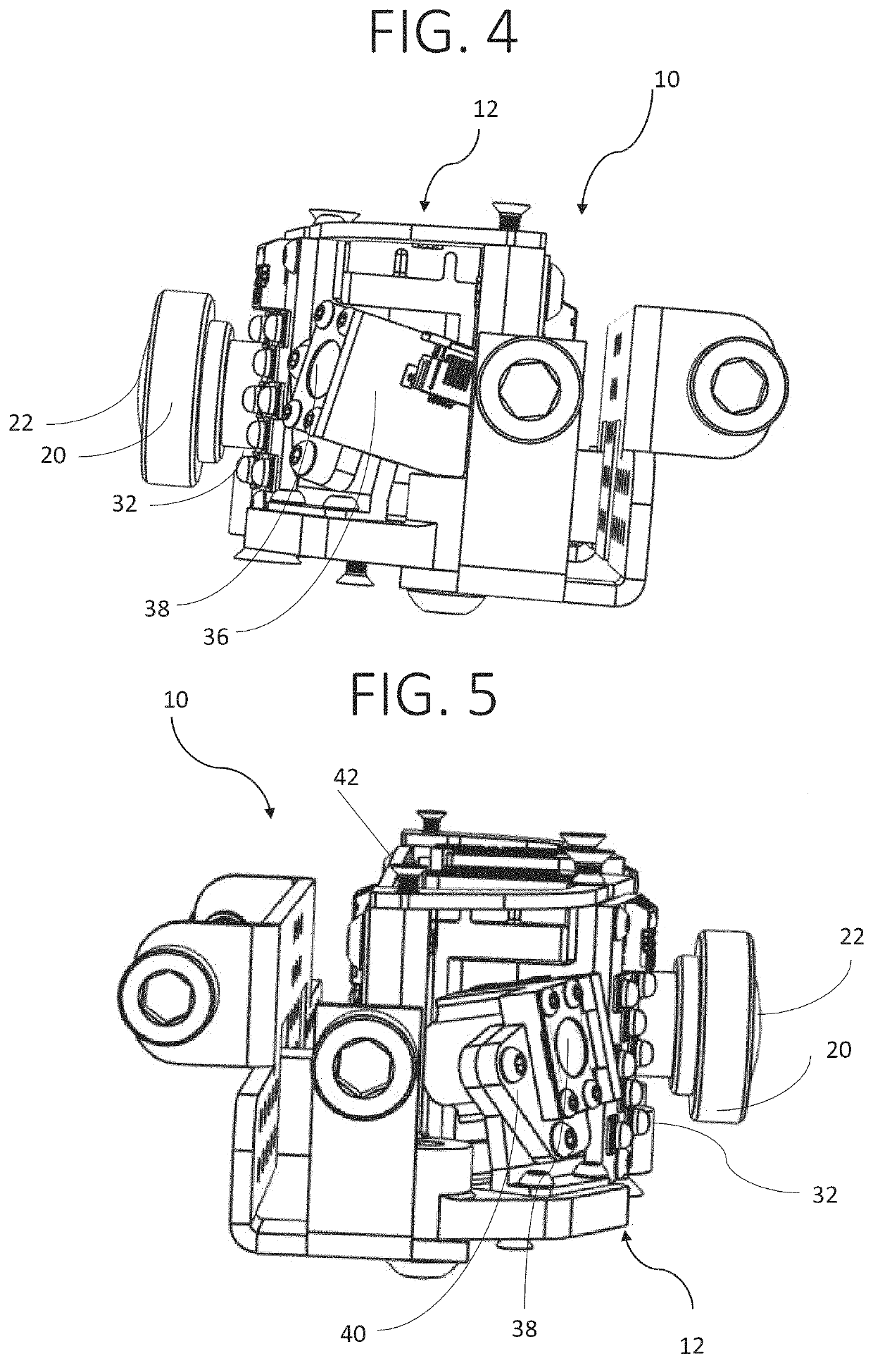
[0029]In another implementation according to the second aspect, the plurality of structured light sources comprises two structured light sources, and the transmitting step comprises transmitting a structured light pattern from each of the two structured light sources onto approximately half of a field of view of the camera. Advantageously, dividing the field of view of the camera between two structured light sources mitigates the challenge of producing a diffractive optical element with a large field of regard or field of view, because each structured light source needs to be spread only through half the vehicle. In addition, the power consumption and heat generated by each of the structured light sources is similarly reduced. Another advantage of this embodiment is that it permits creation of a symmetric structure for the device as well as for the generated structured light pattern, which simplifies the development of an algorithm for analyzing the images. The generated structured light pattern may also assume a more rounded shape, because the center of each structured light source is tilted to the side of the center of the vehicle.

Problems solved by technology

Such limitations may result from considerations such as minimization of size, ensuring adequate field of view, and accounting for heat generated by the optical components.
It is difficult to produce a single laser and diffractive optical element capable of covering a large field of view.
First, it is challenging to produce a diffractive optical element that is able to diffract the laser pattern across such an angular span of a typical passenger vehicle, while simultaneously preserving eye safety limits.
In particular, increasing the field of view for diffractive optical elements may result in tighter requirements for manufacturing tolerances.
Due to manufacturing limitations, such requirements might cause reduced performance, such as an increase in the amount of light that is transmitted in the diffractive optical element's zero-order power (i.e., without any diffraction), which leads to a violation of eye safety limits.
Second, the structured light source, such as a laser, in such a system consumes a relatively large amount of power, and generates excess heat.
Another challenge in producing vehicular monitoring systems is managing the heat generated by each of the components of the system, such as the laser, LEDs, the camera, and the control elements.
Yet another challenge in producing vehicular monitoring systems is that stray light can propagate through plastic elements to a lens of a camera.

Method used


Image

  • Device for monitoring vehicle occupant(s)
  • Device for monitoring vehicle occupant(s)
  • Device for monitoring vehicle occupant(s)

Examples


Embodiment Construction

[0049]The present invention, in some embodiments thereof, relates to a device for monitoring one or more vehicle occupants, and more particularly, but not exclusively, to a device for monitoring one or more vehicle occupants that is mountable in the roof of a car.

[0050]Before explaining at least one embodiment of the invention in detail, it is to be understood that the invention is not necessarily limited in its application to the details of construction and the arrangement of the components and / or methods set forth in the following description and / or illustrated in the drawings and / or the Examples. The invention is capable of other embodiments or of being practiced or carried out in various ways.

[0051]As used in this disclosure, the term “optical component” includes any device suitable for generating light or for capturing light as part of an optical system, including, but not limited, to a laser, an LED, or a camera.

[0052]As used in this disclosure, the term vehicle means a road b...


PUM


Abstract

A device for monitoring occupants of seats in a passenger compartment of a vehicle comprises a heat sink divided into a plurality of sections. Each of the sections comprises a base and cooling fins. The bases extend along a common axis and define a central niche therebetween. Structured light sources are attached to the sections. The structured light sources have an optical element for forming a structured light pattern. The structured light sources are oriented along the common axis and at oblique angles to the central niche, such that the structured light patterns, in combination, are directed such that they would cover occupants of seats of the vehicle. A camera is attached to the niche and configured to capture image patterns resulting from distortion of the plurality of structured light patterns by the occupants of the seats.

Description

FIELD AND BACKGROUND OF THE INVENTION[0001]The present invention, in some embodiments thereof, relates to a device for monitoring one or more vehicle occupants, and more particularly, but not exclusively, to a device for monitoring one or more vehicle occupants that is mountable on the roof of a car.[0002]Automated object detection methods and systems, especially for monitoring people in a vehicle, are attracting a continuously growing attention as they may be applied for a plurality of systems, services and / or applications ranging from commercial applications, entertainment applications to automated and / or autonomous vehicles and many more.[0003]This application makes reference to International Application No. IL2018 / 051307 (Publication WO2019 / 111244) entitled “Systems and Methods for Adjustment of Vehicle Sub-Systems Based on Monitoring of Vehicle Occupant(s)” filed Nov. 29, 2018, which claims priority to U.S. Provisional Patent Application No. 62 / 594,043 entitled “Vehicle Intra P...

Claims


Application Information

Patent Timeline
Patent Type & Authority Patents(United States)
IPC IPC(8): H04N7/18H04N5/225G06K9/20G06K9/00G06V10/145
CPCH04N7/18G06K9/00838G06K9/2036H04N5/2253H04N5/2256H04N7/183G06V40/20G06V20/593G06V10/145H04N23/52H04N23/57H04N23/56H04N23/54
Inventor AMIRAM, YOTAMZUTA, YOAVRAZ, GUY
Owner GENTEX CORP
Learn More