Method of position planning for a recording system of a medical imaging device and medical imaging device

a technology of medical imaging and recording system, applied in the field of position planning of medical imaging device recording system, can solve the problems of inflexible methods and limited reconstruction volume of mobile c-arms, and achieve the effects of improving patient care, simplifying clinical workflow, and simplifying workflow

Active Publication Date: 2022-04-26
SIEMENS HEALTHCARE GMBH
View PDF8 Cites 0 Cited by
  • Summary
  • Abstract
  • Description
  • Claims
  • Application Information

AI Technical Summary

Benefits of technology

[0021]According to a further embodiment, a correctly positioned superimposition of previously made recordings of the patient is performed on a display unit. In this connection, for example, preoperatively created 2D recordings or 3D scans (e.g., CT or MRT) may be corrected in terms of position and / or may be superimposed on the patient in original size for the purpose of better orientation. This may be advantageous if, for example, particular regions are to be recorded again for control purposes in order, for example, to check the position of implants or to operate on a tumor. Size comparisons of relevant structures with respect to the change since the last recording are also made possible hereby. It may also be advantageous that the physician has already marked the position of relevant structures in a corresponding planning system before the procedure and a control unit then already determines (e.g., in the OP with knowledge of the patient position) the necessary recording positions of the imaging device (e.g., mobile C-arm) for intraoperative 2D recordings or 3D scans.
[0022]The method of one or more of the present embodiments simplifies clinical workflows in that the currently conventional, laborious positioning interaction with the imaging device (e.g., C-arm) is largely eliminated and replaced by a patient- or image-centered approach. The optimum device position is automatically determined in the process. Volume-capturing camera systems and optionally AR glasses, for example, are used as aids. The method serves as an intuitive, clear, and fast positioning aid for a user or an operator of a medical imaging device to simplify workflows and improve patient care.
[0024]According to one embodiment, the device also includes a tracking system for acquiring current position information of the recording system and / or the imaging device and / or setting information of a collimator, and for acquiring current position information of the patient. A tracking system of this kind may be formed, for example, by a 3D camera (e.g., an external camera) or augmented reality glasses. An external 3D tracking camera may also rely on, for example, suitable marker structures that are fastened, for example, to the patient and the recording system (e.g., a C-arm) (e.g., outside-in tracking). It is also possible to use corresponding tracking hardware as is used in mixed reality or augmented reality (AR) glasses (e.g., MS HoloLens) (e.g., inside-out tracking). A combination of the two methods is also possible to increase the robustness.

Problems solved by technology

These methods are not very flexible, however, and require the user to manually adjust the position of the imaging system until the desired target region for recording is reached.
This is sometimes a problem, for example, with mobile C-arms with a spatially very limited reconstruction volume (e.g., cube with approximately 16 cm edge length in the case of Cios Spin) if relatively large target structures are to be depicted by a scan.

Method used


Image

  • Method of position planning for a recording system of a medical imaging device and medical imaging device
  • Method of position planning for a recording system of a medical imaging device and medical imaging device
  • Method of position planning for a recording system of a medical imaging device and medical imaging device

Examples


Embodiment Construction

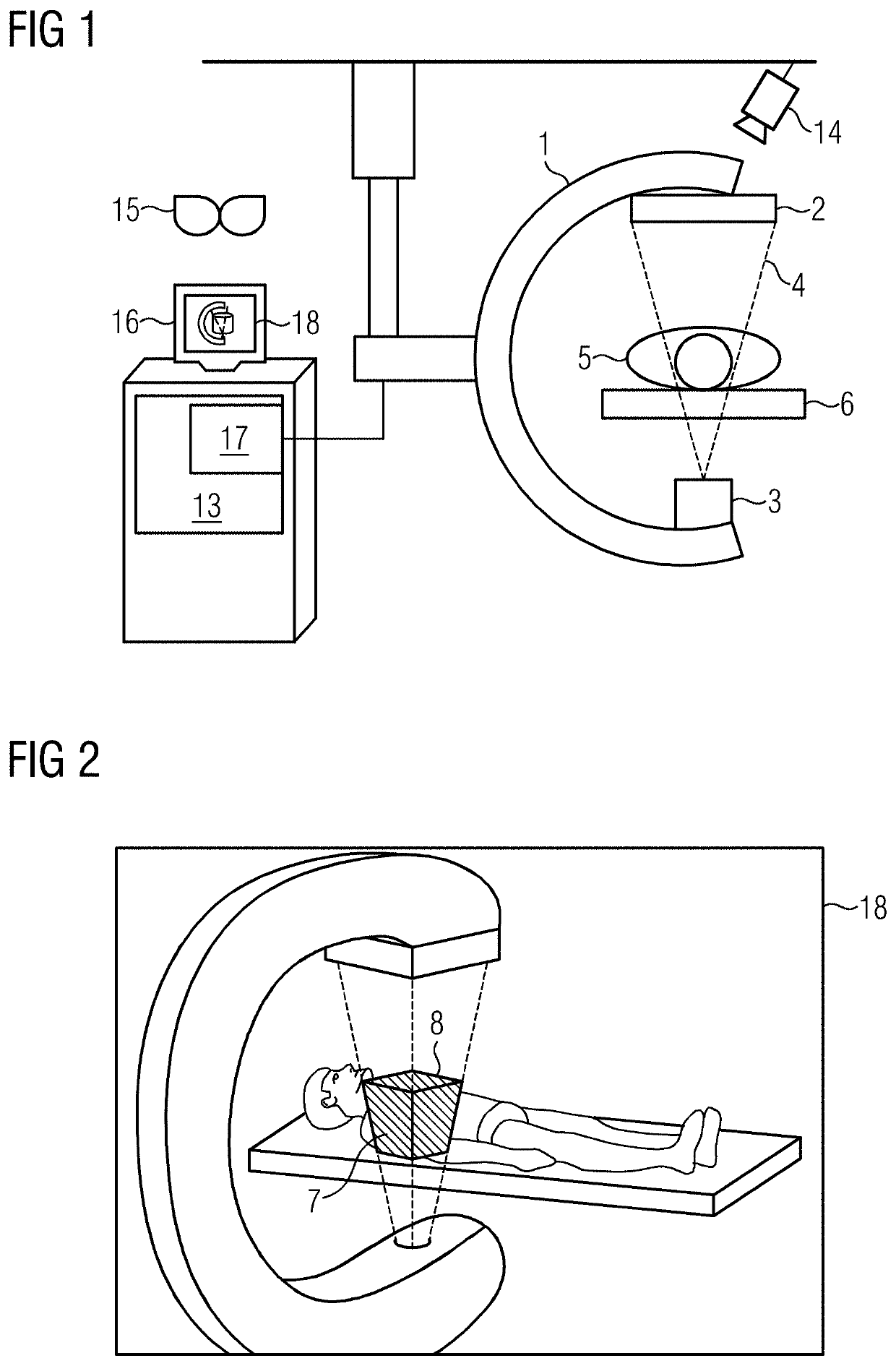
[0033]FIG. 1 shows one embodiment of a medical imaging device with a C-arm 1, to which an X-ray detector 2 and an X-ray source 3 are fastened. The X-ray source 3 may emit an X-ray beam 4 additionally shaped or shapeable by a collimator (not shown). The X-ray beam 4 penetrates a patient 5 supported on a patient couch 6. A position and / or a covering of the C-arm and a position of the patient 5 (e.g., in the form of a patient covering) are acquired, for example, by an acquisition system (e.g., a tracking system with a three-dimensional (3D) tracking camera 14). The recording system (e.g., the C-arm 1 with the X-ray source 3 and the X-ray detector 2) may be moved with respect to the patient 5 (e.g., may be rotated and translated). The recording system may be fastened, for example, by a bracket to the ceiling, the floor, or a device trolley. The imaging device is controlled by a system controller 13 that controls emission of the X-ray radiation and movements of the recording system (e.g....


PUM


Abstract

A method of position planning for a recording system of an imaging device with respect to a selectable field of view of a patient includes acquiring current position information of the recording system and / or the imaging device, and / or setting information of a collimator of the imaging device. A current intersection volume between an X-ray beam and the patient and / or a current field of view is determined. The current intersection volume and / or the current field of view is determined as a virtual display element. A target intersection volume and / or a target field of view is received by manipulation of the virtual display element. A target position of the recording system and / or the imaging device, and / or the setting of the collimator is determined, such that, on occupying the target position, the target intersection volume and / or the target field of view becomes the current intersection volume and / or current field of view.

Description

[0001]This application is the National Stage of International Application No. PCT / EP2018 / 081864, filed Nov. 20, 2018, which claims the benefit of European Patent Application No. EP 18154435.4, filed Jan. 31, 2018. The entire contents of these documents are hereby incorporated herein by reference.BACKGROUND[0002]The present embodiments relate to position planning for a recording system of a medical imaging device.[0003]Imaging medical devices (e.g., permanently installed radiography systems or mobile C-arm devices) nowadays typically use the following techniques to preview the region of the body of the patient to be recorded. For example, the 2D field of view may be displayed by projection directly onto the patient. This is usually achieved by a plurality of line lasers or the projection of a light “window” directly onto the surface of the patient. The projection hardware is installed in the imaging device for this purpose (e.g., on the image recorder and / or emitter housing). As anot...

Claims


Application Information

Patent Timeline
Patent Type & Authority Patents(United States)
IPC IPC(8): A61N5/10G06T7/33A61B6/00A61B6/06G06T19/00
CPCA61B6/547A61B6/06A61B6/4405A61B6/4441A61B6/466A61B6/469G06T19/006G06T2219/2004
Inventor SCHWEIZER, HANSSCIPIO, CHRISTIANMAYER, HERMANN GEORGHEINRICH, VERONIKA
Owner SIEMENS HEALTHCARE GMBH
Why Eureka
Try Eureka